
What is profile milling?
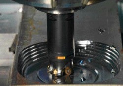
Profile milling is a common milling operation. Round inserts and concepts with radius are milling cutters used for roughing and semi-roughing while ball nose end mills are milling cutters used for finishing and super-finishing.
Profile milling process
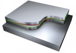
Profile milling covers the multi-axis milling of convex and concave shapes in two and three dimensions. The larger the component and the more complicated the configuration of the machine, the more important the planning of the profile milling process becomes.
The machining process should be divided into at least three operation types:
- Roughing/semi-roughing
- Semi-finishing
- Finishing
Super-finishing, often performed using high-speed machining techniques, is sometimes required. The milling of remaining stock, called rest milling, is included in semi-finishing and finishing operations. For best accuracy and productivity, it is recommended that roughing and finishing are performed in separate machines, and optimized cutting tools are used for each operation.
The finishing operation should be carried out in a 4/5-axis machine tool with advanced software and programming techniques. This can considerably reduce or even completely eliminate time-consuming manual completion work. The final result will be a product with better geometrical accuracy and a higher surface structure quality.
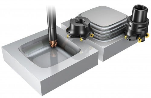
Choice of tools
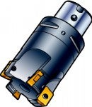
Optimized cutting tools for roughing and semi-roughing:
round inserts and concepts with radius.
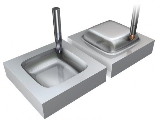
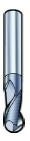
Optimized cutting tools for finishing and super-finishing:
ball nose end mill and concept with radius.
 |  |  |  | |
| Round inserts | Ball nose indexable | Ball nose exchangeable head | Ball nose solid carbide | |
| Machine / Spindle size | ISO 40, 50 | ISO 40, 50 | ISO 30, 40 | ISO 30, 40 |
| Stability requirement | High | Medium | Medium | Low |
| Roughing | Very good | Good | Acceptable | Acceptable |
| Finishing | Acceptable | Acceptable | Very good | Very good |
| Cutting depth ap | Medium | Medium | Small | Small |
| Versatility | Very good | Very good | Very good | Very good |
| Productivity | Very good | Good | Good | Good |
Application checklist for profile milling
The profile of the component should be studied carefully in order to select the right tools and find the best-suited machining method:
- Define minimum radii and maximum cavity depth
- Estimate the amount of material to be removed
- Consider tool setup and clamping the workpiece in order to avoid vibrations. All machining should be performed on optimized machines to achieve good geometrical accuracy on the profile
- By using separate, accurate machine tools for finishing and super-finishing operations, the need for time-consuming manual polishing can be reduced, or in some cases eliminated
- Some advanced programming may be necessary to obtain large savings. Use a solid carbide end mill with high-speed technique to machine near-net shapes and achieve the best possible finish
- Roughing and semi-finishing of large components are, as a rule, most productively done with conventional methods and tooling. An exception is aluminum, for which high cutting speeds are also used for roughing
How to reduce vibrations
Vibration is an obstacle in milling deep profiles using long overhangs. Common methods to overcome this problem are to reduce depth of cut, speed or feed.
- Use stiff modular tools with good run-out accuracy
- Modular tools increase the flexibility and possible number of combinations
- Use damped tools or extension bars when total tool length, from the gauge line to the lowest point of cutting edge, exceeds 4−5 times the diameter at the gauge line
- Use extensions made of heavy metal, if bending stiffness must be radically increased
- Use balanced cutting and holding tools for spindle speeds over 20,000 rpm
- Choose the largest possible diameter on the extensions and adapters relative to the cutter diameter
- 1 mm (0.039 inch) in radial difference between the holding and the cutting tool is enough. Use oversized cutters
- Plunge milling is an alternative method for milling with extra-long tools
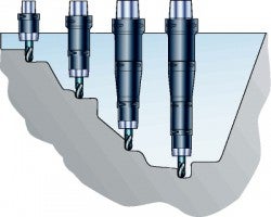
Extend tool length gradually

To maintain maximum productivity in roughing operations where the final pass is located deep in the component, it is important to work with a series of extensions for the cutter.
- Start with the shortest extension, as longer extensions limit productivity and tend to generate vibration
- Change to extended tools at predetermined positions in the program. The geometry of the cavity determines the point of change
- Adapt cutting data to each tool length to maintain maximum productivity
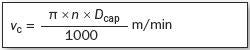
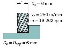
True cutting speed
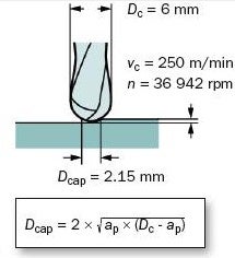
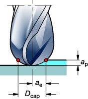
If using a nominal diameter value of the tool when calculating the cutting speed of a ball nose or round insert cutter, the true cutting speed, vc, will be much lower if the depth of cut, ap, is shallow. Table feed and productivity will be severely hampered.
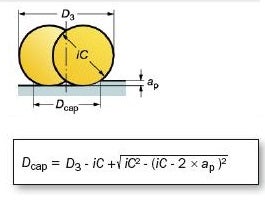
Base calculations for cutting speed based on true or effective diameter in cut, Dcap.
Shoulder end mill
Ball nose cutter
Round insert cutter
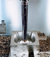
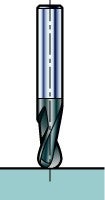
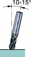
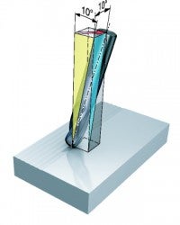
Point milling – tilted cutter
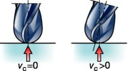
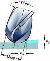
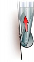
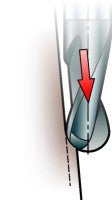
When using a ball nose end mill, the most critical area of the cutting edge is the tool center, where the cutting speed is close to zero, which is unfavorable for the cutting process. Chip evacuation at the tool center is critical, due to the narrow space at the chisel edge.
Therefore, tilting the spindle or the workpiece 10 to 15 degrees is recommended, which moves the cutting zone away from the tool center.
- The minimum cutting speed will be higher
- Improved tool life and chip formation
- Better surface finish
Example of center cutting cutters
Central part, z = 2

Peripheral part, z = 4
Z = 2
Z = 4
Shallow cut
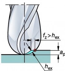
When using a round insert or a ball nose cutter at a lower depth of cut, the cutting speed, vc, can be increased due to the short engagement time for the cutting edge. The time for heat propagation in the cutting zone becomes shorter, i.e. the cutting edge and the workpiece temperature are both kept low. Also, the feed/tooth, fz, can be increased, due to the chip-thinning effect.
Shallow cut
Example shallow cut, non-tilted versus tilted cutter
This example show the possibilities for increasing the cutting speed when the ae/ap is small, as well as the advantages of using a tilted cutter.
Ball nose solid carbide
Dc = 10 mm, grade GC 1610.
Material: Steel, 400 HB
Cutting data recommendation for a deep cut ap – Dc/2:
vc = 170 m/min
fz = 0.08 mm/r = hex
| Operation | Non-tilted cutter | Tilted cutter (10°) |
Semi-finishing ap – 2 mm (0.079 inch)
vc – 300 m/min (984 ft/min)
Feed per tooth, fz, is the same for the both non-tilted and the | Dc = 10 mm (0.394 inch)
vc = 300 m/min (984 ft/min)
hex = 0.08 mm (0.003 inch)
vf = 2,860 mm/min (113 in/min) | Dc = 10 mm (0.394 inch)
vc = 300 m/min (984 ft/min)
hex = 0.08 mm (0.003 inch)
vf =5,100 mm/min (201 in/min) |
Super-finishing ae – 0.1 mm
vc – 5 * 170–850 m/min (557–2,789 ft/min)
Note: In super-finishing, a two-tooth cutter zn = 2, should be
fz – 0.12 mm/z (0.005 in/z) | A non-tilted cutter is not recommended for super-finishing | Dc = 10 mm (0.394 inch)
vc = 850 m/min (2,789 ft/min)
hex = 0.02 mm (0.0008 inch)
vf =14,600 mm/min (575 in/min) |
Productivity in profile milling: constant stock
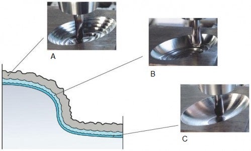
A: Roughing
B: Semi-finishing
C: Finishing and super-finishing
A constant stock is one of the truly basic criteria for high and constant productivity in profile milling, especially when using high speeds.
- To reach maximum productivity in these operations, common in die- and mold-making, it is important to adapt the size of the milling cutters to specific operations
- The primary goal is to create an evenly-distributed working allowance, or stock, to obtain few changes in work load and direction for each tool used
It is often more favorable to de-escalate the sizes on different cutters, from bigger to smaller, especially in light roughing and semi-finishing, instead of using only one diameter throughout each operation.
- The best quality in finishing is achieved when preceding operations leave as little and as constant amount of stock as possible
- The goal should always be to come as close as possible to the requirements specified for the final shape
- Safe cutting process
Benefits with a constant stock
- Some semi-finishing and practically all finishing operations can be performed partially manned, or even sometimes unmanned
- Impact on the machine tool guide ways, ball screws and spindle bearings will be less negative
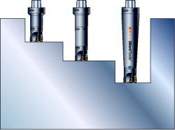
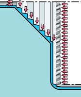
Opening up from a solid workpiece
- When opening up a cavity, it is important to choose a method that minimizes ap, and also leaves a constant stock for the subsequent profile milling operation
- Shoulder face/end mills or long-edge cutters will leave a staircase stock that has to be removed. This generates varying cutting forces and tool deflections. The result is an uneven stock for finishing, which will influence the geometrical accuracy of the final shape
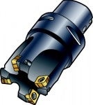
- Use of round insert cutters will generate smooth transitions between the passes and leave less stock in more even quantities for the profiling operation, resulting in better component quality
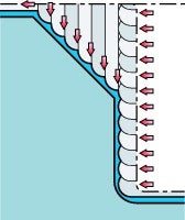
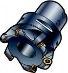
- A third alternative is to use a high-feed cutter to open the cavity. This will also result in a small and even, constant stock, due to the small depth of cut, i.e. small staircase steps
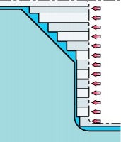
Square shoulder cutter,
larger and uneven stock remaining
Round insert cutter,
small stock remaining
High cutter feed,
small stock remaining
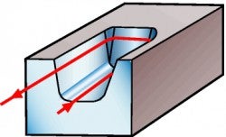
Copy milling
The traditional and easiest method for programming tool paths for a cavity is to use the normal copy milling technique, with many entrances and exits into the material. However, this means that powerful software programs, machines and cutting tools are used in a very limited way. It is preferable to use a machine with software that has look-ahead functions, to avoid tool path deviations.
An open-minded approach to the choice of methods, tool paths, milling and holding tools is essential.
− Heavy load on the insert center point
− Reduced feed rates
− Reduced tool life
− Mechanical impact
− Form errors
− Longer programs and cutting time
A copy milling tool path is often a combination of up- and down-milling, and requires a lot of unfavorable engagements and disengagements in the cut. Each entrance and exit means that the tool will deflect, leaving an elevated mark on the surface. The cutting forces and the bending of the tool will then decrease, and there will be a slight undercutting of material in the exit area.
Conclusions
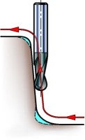
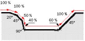
- Copy milling along steep walls should be avoided as much as possible. When plunging, the chip thickness is large and cutting speed should be low
- There is a risk of edge frittering at the tool center, especially when the cutter hits the bottom area
- Use a feed speed control with a look-ahead function. Otherwise, the deceleration will not be fast enough to avoid damages to the tool center
- There will be a large contact length when the cutter hits the wall, with risk for deflection, vibration or tool breakage
- When using ball nose end mills, the most critical area is at the tool center, since the cutting speed is zero. Avoid using the tool center area and apply point milling by tilting the spindle or the workpiece to improve the conditions
- It is somewhat better for the cutting process to perform up-copying along steep walls, as the chip thickness has its maximum at a more favorable cutting speed
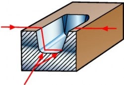
Risk for gouging
Up-copying:
Maximum chip thickness at recommended vc.
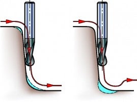
At bottom of cavity:
Risk of frittering at tool center.
Form errors are common, especially when using a high-speed machining technique.
Down-copying:
Large chip thickness at very low vc.
Feed reduction to avoid shortened tool life
Reversed up- and down-milling will expose the tool to alternating deflection and cutting forces. By reducing the feed rate in the critical sections of the tool path, the risk for edge frittering is reduced, and a safer cutting process with longer tool life is achieved.
Contour milling
Instead of using programming techniques that are limited to “slicing off” material at a constant Z-value, it is highly advantageous to use contouring tool paths in combination with down-milling. The results include:
+ A considerably shorter machining time
+ Better machine and tool utilization
+ Improved geometrical quality of the machined shape
+ Less time-consuming finishing and manual polishing work
+ Cutting speed control - ve
+ Enabling HSM
+ High feed rates
+ Long insert life
+ Security
The initial programming work is more difficult and will take somewhat longer; however, this is quickly recouped as the machine cost per hour is normally triple that of a workstation. It is preferable to use a machine with software that has look-ahead functions, to avoid tool path deviations.Conclusions
- Use a contouring type of tool path, such as “Waterline milling”, as the best method to ensure down milling
- Contouring with the periphery of the milling cutter often results in higher productivity, as more teeth are effectively in the cut on a larger tool diameter
- If the spindle speed is limited in the machine, contouring will help maintain and control the cutting speed
- Contouring also creates fewer quick changes in the work load and direction. In high-speed and feed milling, and in hardened materials, this is of specific importance, as the cutting edge and the process are more vulnerable to any changes that can create differences in deflection or create vibration
- For good tool life, stay in the cut continuously, and for as long as possible
Note! Avoid cutting with the center of the tool when cutting speed is zero.
Tool path strategy
Z – constant contouring, two axes. Roughing to finishing
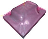
Waterline milling Z – constant contouring
- Common when CAM-controlled maximum scallop function is available
- Smooth engagement and retraction
- Easy programming
- Wide tool choice
Helical contouring, three to five axes. Finishing
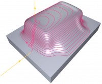
Contouring in a ramping tool path
- Smooth changes of direction
- Good form accuracy and surface finish
- Controlled scallop height
- Constant engagement
- Short programs
- Short tool
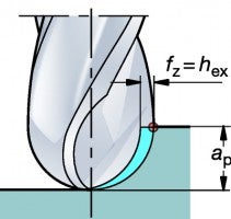
Generation of sculptured surfaces
Down milling with a cutter tilted approx. 10° in two directions ensures a good surface finish and reliable performance. A ball nose cutter or a radius-shaped cutting edge will form a surface with a certain cusp height, h, depending on:
- Width, ae, of cut
- Feed per tooth, fz
Other important factors are the depth of cut, ap, which influences the cutting forces and the tool indicator reading of the run-out – TIR. For best results:
- Use high-precision hydraulic chuck with Coromant Capto®
- Minimize tool overhang
Roughing and semi-roughing
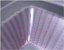
If the feed per tooth is much smaller than the width and depth of cut, the surface generated will have a much smaller cusp height in the feed direction.
Finishing and super-finishing
It is beneficial to achieve a smooth, symmetrical surface texture in all directions, which can be easily polished afterwards, regardless of the polishing method selected.
This is obtained when fz ≈ ae.
Always use a tilted, two-tooth cutter in super-finishing to achieve the best surface texture.
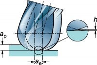
Semi-roughing with fz much smaller than ae
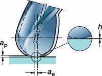
Super-finishing with a tilted cutter and fz equal to ae
Milling
When evaluating a successful outcome within milling applications, it is very much... chevron_right
Shoulder milling
Shoulder milling operations include: Shoulder / face milling Edging peripheral... chevron_right
Thread milling application tips
To achieve the best results in thread milling operations, always consider the following... chevron_right
Milling inserts and grades for stainless steel
A tough, PVD-coated grade with thin coating for roughing to finishing in unstable... chevron_right
