
Turn milling
What is successful turn milling?
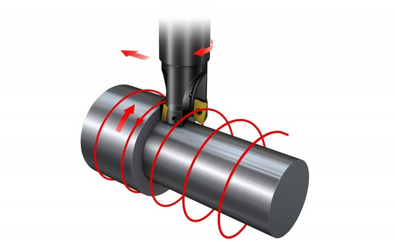
Turn milling is defined as the milling of a curved surface while rotating the workpiece around its center point.
Eccentric forms or shapes that differ considerably from those produced by conventional milling or turning operations can often be turn milled. The method allows for high metal removal with superb chip control.
- A cylindrical surface can be produced only when feeding the milling cutter in a radial direction during rotation
- By simultaneously moving the cutter in two directions, it is possible to produce eccentric surfaces, e.g. cams on shafts
- Movement along more than 2 axes requires a tool with ramping capabilities
- To machine a conical shape, 5 axes are required
- Turn milling of complex profiles, e.g. turbine blades, requires simultaneous movement along 5 (or 4) axes: 2 or 3 for the workpiece and 1 or 2 for the tool
- It is possible to produce components such as turbine blades by feeding the cutter along more than 2 axes while simultaneously rotating the component
Choice of turn milling process
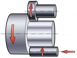
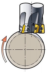
Face turn milling – 4/5 axes
Main method for external machining.
+ Short tool extensions
+ Smaller tool diameters/low torque
+ External/slender components
+ Profiling
− Not a natural cylindrical surface
− Internal
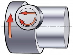
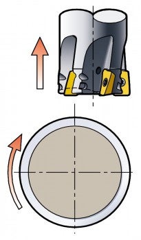
Periphery turn milling – 3/4 axes
Same principle as for circular interpolation (internal/external), but in turn milling, both the workpiece and the cutter rotate.
Used mainly for internal features.
+ Internal machining
+ Cylindrical surface
+ Narrow slots
+ Thread milling
+ Roundness
− Profiling
− Larger diameters/high torque
− Long overhangs
How to apply turn milling
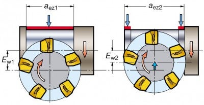
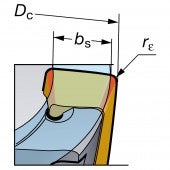
Cutter position – rectangular inserts/wiper
Location of cutter
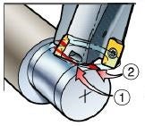
Width of cut
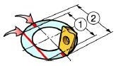
1 = First cut
2 = Second cut
In face turn milling operations, one wiper insert is used to generate the straight line contact between the cutter and the machined surface in order to create the cylindrical part of the component.
Because the milled surface is convex, the wiper land needs to be flat instead of crowned. To cover the full width of the cutter, the tool needs to be placed with at least two offsets, first Ew1 during the first revolution of the workpiece and then moved to Ew2 for a second cut.
Cutter position – round inserts/non wiper
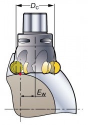
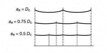
For producing the flattest possible surface in turn milling operations, a small diameter cutter with a width of cut, ae, less than 40% of the effective cutter diameter, DC, is optimal.
However, the ae needs to be increased in order to obtain the best productivity. This can be done by increasing:
- Cutter diameter
- Ratio of radial engagement – ae/DC
To gain acceptable cusp height, the cutter needs to be offset from the center. The amount of offset depends on the ae and is taken from the diagram for the respective ae/DC.
Offset and width of cut
Wiper width
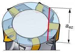
Width of cut
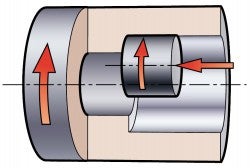
When milling a surface that is wider than the cutter diameter, it is necessary to remain in the initial position and then to move the cutter in the axial direction to the required length, which is, however, not more than 80% of the aez1 per revolution. If a 90° shoulder is required, the cutter has to move to second a position, Ew2.
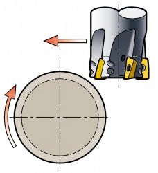
Infeed principle
During the turn milling process, the milling tool should be fed into the workpiece in the radial direction. The workpiece rotation speed should correspond to the feed/tooth recommended for the insert. The cutter should be fed out axially.
Milling
When evaluating a successful outcome within milling applications, it is very much... chevron_right
Groove or slot milling
Groove or slot milling is an operation in which side and face milling is often preferred... chevron_right
Milling
Product overview There is a wide range of Silent Tools milling adaptors available... chevron_right
Thread milling
Thread milling produces threads with the circular ramping movement of a rotating... chevron_right
