Ramping: two axis linear and circular
What is successful ramping?
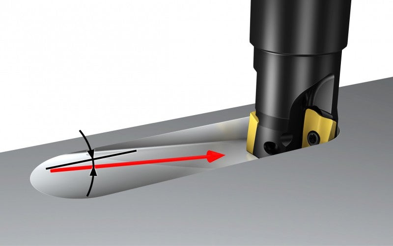
Linear ramping is a commonly used, efficient way of approaching the workpiece when machining closed slots/pockets/cavities. It even eliminates the need for a drill.
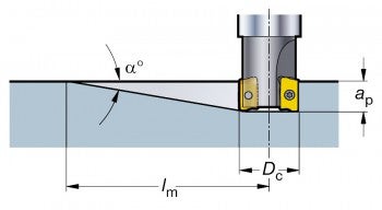
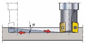
Linear ramping is defined as simultaneous feeding in the axial direction (Z) and in one radial direction (X or Y), i.e. two-axis ramping.
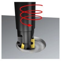
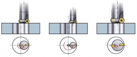
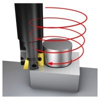
Circular ramping (also called helical interpolation, spiral interpolation, orbital drilling, etc.) is a simultaneous movement along a circular path (X and Y) together with an axial feed (Z) at a defined pitch. It is also an alternative to drilling.
Circular ramping is always preferred to linear ramping (full slotting), because helical interpolation is a much smoother process, as the radial cut is reduced. It allows for pure down-milling and provides better chip evacuation. Counterclockwise rotation ensures down-milling.
Two-axis ramping – linear
How to apply rampingA demanding cutting process
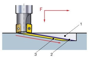
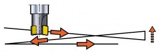
There are three cutting processes that occur simultaneously during the linear ramping operation:
1) Periphery cutting with the leading insert.
2) Bottom cutting with the leading insert.
3) Bottom cutting with the trailing insert.
The cutting forces are both axial and radial.
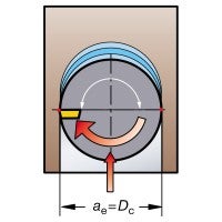
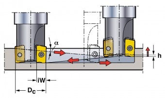
There is also added stress on the tool due to full slotting, which means that ae = Dc, creating large radial forces and long chips.
Machining recommendations
- Reduce feed to 75% of normal feed rate
- When slot milling is performed directly after ramping, it is important to continue at a lower feed for a distance that corresponds to the cutter diameter, until the trailing insert has stopped cutting
- Use cutting fluid to help with chip evacuation
- Reduce the tool radius to reduce the area of contact
- Linear ramping should be limited to narrow slots less than 30 mm wide if access for circular ramping is limited
Progressive ramping
When ramping for several passes to produce a deep slot, productivity can be easily increased by ramping in both directions (progressive ramping) instead of ramping in only one direction (single pass ramping).
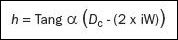
Note: When feeding the cutter at the maximum ramping angle, it must be lifted a distance of h before changing direction. This prevents damage to the central part of the cutter body.
Single-pass ramping.
Tool path correction
Progressive ramping at the maximum ramping angle.
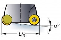
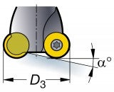
The insert radius affects the maximum ramping angle
Example:
The curves in the diagram are valid for minimum and maximum radii. For intermediate radii, please interpolate.
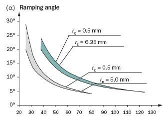
Tool diameter, Dc mm

= Insert size 22

= Insert size 16
Two-axis ramping – circular
Process considerations
There are three key considerations in circular ramping; if not correctly applied, problems will occur.
- Cutter diameter selection for hole size
- Pitch per revolution
- Feed rate
1. Cutter diameter selection for hole size
The cutter size selection is very important when using cutters that are not center cutters. Cutter diameter ensures that the insert cuts over the center line of the hole.
Cutter diameter is too small and will leave a core in the middle – like trepanning. This is acceptable for large cut-outs (‘man holes’), but the core needs to be supported as it drops off.
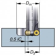
If the cutter is too large, the insert does not inscribe the center line of the hole and a pip will be formed that will foul on the bottom of the cutter.Maximum diameter hole
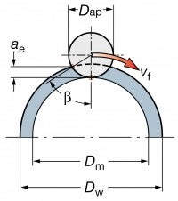
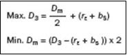
- The maximum hole diameter, Dm, that can be produced in one continuous spiral, is 2 x D3
- This is full slotting and will leave a pip at the center of a blind hole
- The pip is removed by feeding to the center, for a flat bottom
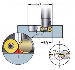
Max. hole diameter Dm

Milling diameter flat bottom
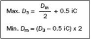
- Ensure that no pip is left on the bottom of a blind hole; the insert radius size needs to be considered
- If the cutter is too big, the pip cannot be removed by feeding to the center
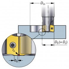
Min. hole diameter Dm
Min. hole diameter Dm
Minimum diameter through hole
- The minimum diameter that avoids cutter body collision due to non-center cutting
- b is the maximum stepover allowed for plunging and is the same for the maximum overlap
- For round inserts, b should be calculated as b = 0.8 x iC
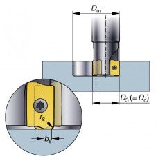
- The pip cannot be removed.
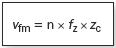
2. Pitch (P)
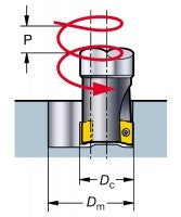
The pitch can never be larger then the maximum ap for the cutter concept, and depends on the hole diameter, the cutter diameter and the ramp angle.
3. Feed rate
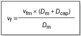
The feed value always depends on the hex value, which corresponds to the peripheral feed rate, vfm. However, many machines require a tool center feed, vf, which has to be calculated accordingly:
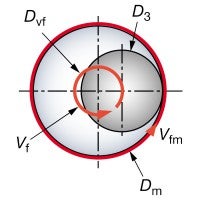
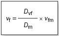
Dvf = programmed cutter path
Programmed feed rate:
vfm = when using radius compensation
vf = when using the tool center feed
Circular external ramping
External circular ramping (3-axis)
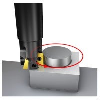
External circular milling (2-axis)
What is successful circular external ramping?
Compared to internal circular milling/ramping:
- The tool center feed, vf, is increased instead of reduced
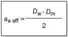
- The radial depth, ae, becomes much smaller when milling externally; therefore, a higher cutting speed can be used
- hex is calculated in the same way as for edging
- The programming technique is otherwise very similar to the internal milling of holes