
How to reduce vibration in milling
Milling vibration can arise due to limitations in the cutting tool, the holding tool, the machine, the workpiece or the fixture. To reduce vibration, there are some strategies to consider.
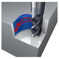
The cutting tool
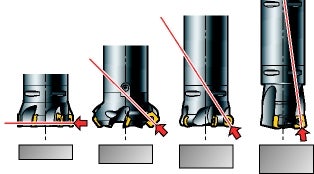
- With 90° cutters, the dominant forces focus in the radial direction. This creates deflection of the cutter at long overhangs; however, the small axial force is advantageous when milling thin-walled/vibration-sensitive components
- 45° cutters generate evenly distributed axial and radial forces
- Round insert cutters direct most of the forces up the spindle, particularly at small depths of cut. Also, 10° cutters transmit the forces primarily into the spindle, which reduces vibrations generated due to long tool overhangs
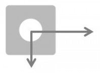
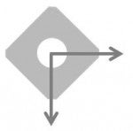

- For face milling, the direction of the cutting forces must be considered:
- Choose the smallest diameter possible for the operation
- DC should be 20–50% greater than ae
- Choose a coarse pitch and/or a differential-pitched cutter
- A cutter with a low weight is advantageous e.g. a cutter with aluminum body
With thin-walled, unstable workpieces, use a large entering angle = small axial cutting force.
At long tool overhangs, use a small entering angle = high axial cutting force.
The holding tool
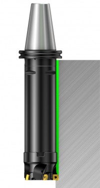
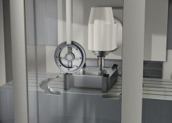
The Coromant Capto® modular holding tool system enables tools to be assembled with the required length while maintaining high stability and smallest possible run-out.
- Keep the tool assembly as rigid and short as possible
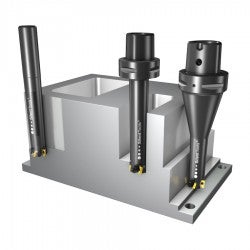
- Choose the largest possible adapter diameter/size
- Use Coromant Capto® adapters with oversized cutters to avoid reduction adapters
- For small milling cutters, use a tapered adapter if possible
- In operations where the final pass is located deep in the component, change to extended tools at predetermined positions. Adapt cutting data for each tool length
- For spindle speeds over 20,000 rpm, use balanced cutting and holding tools
Oversized cutter
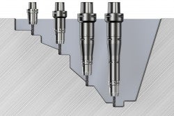
Always use the shortest possible tool length.
Extend length successively.
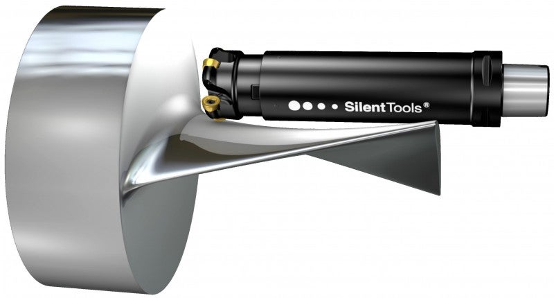
Silent Tools dampened milling cutters
For overhangs greater than four times the tool diameter, milling vibration tendencies can become more apparent, and Silent Tools damped cutters can dramatically improve productivity.
The cutting edge
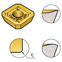
To reduce the cutting forces:
- Choose a light cutting geometry, -L, with a sharp edge and a grade with a thin coating
- Use inserts with small corner radii and small parallel lands
Sometimes adding more damping to a system can decrease the vibration tendencies. Use a more negative cutting edge geometry and a slightly worn cutting edge.
Cutting data and tool path programming
- Always position the cutter off-center in relation to the milled surface
- With KAPR, 90° long edge cutters or end mills, use low radial immersion: max ae = 25% DC and high axial cut; max ap = 100% De
- In face milling, use a small depth of cut, ap, and high feed, fz, with round inserts or high feed cutters with small entering angles
- Avoid vibrations in corners by programming a large path radius, see milling inside corners
- If the chip thickness becomes too low, the cutting edge will rub rather than cut, causing vibration. In such instances, the feed per tooth should be increased
The machine tool
The machine condition can have a large influence on milling vibration tendencies. Excessive wear on the spindle bearing or feed mechanism will result in poor machining properties. Choose machining strategies and cutting force directions carefully to take full advantage of the machine stability.
Each machine spindle has natural areas that are prone to vibration. The areas of stable cutting are described as stability lobes, and they increase as the rpm increases. Even a small increase, as low as 50 rpm, can change a cutting process from unstable, with vibration, to stable.
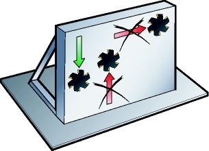
The workpiece and its fixture
Consider the following when milling components with a thin wall/base and/or when the fixture is weak:
- The fixture should be close to the machine table
- Optimize the tool path and feed direction towards the machine's/fixture’s strongest node to obtain the most stable cutting conditions
- Avoid machining in directions in which the workpiece is poorly supported
- Up milling can reduce vibration tendencies when the fixture and/or workpiece are weak in a specific direction
For weak fixtures, use a feed direction into
the machine table
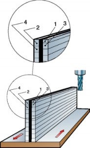
Note that the first step should be made at
half the depth of the second, third, etc.
Internal grooving tools
Avoid vibration and get good chip control. Dampened boring bars and light cutting... chevron_right
Machining centers
When using a machining center, our solutions will help you increase efficiency, reduce... chevron_right
Turning tools
Our turning tools control chips, tool life and vibration – leading to improved processes... chevron_right
CoroMill® MH20
The versatile concept, suitable for all types of high-feed milling operations, helps... chevron_right
