
Tool balancing and RPM
Increased cutting speeds combined with higher balancing requirements result in tighter balancing conditions for the total tool system—machine spindle, clamping device and tool system.
Tool balancing requirements
Balancing, according to ISO 1940-1, can often be additionally improved by choosing the next-better balancing grade (e.g. G 2.5 instead of G 6.3). Not only is this often technically unnecessary, leading to high costs, but in many cases, it also cannot be achieved.
Another point of consideration for qualifying the spindle load due to unbalance is that dynamic cutting forces (e.g. caused by the interrupted cut of a milling cutter) are often remarkably higher than the centrifugal forces caused by necessary permissible residual unbalances. The unbalance acts as a speed-harmonic excitation of the machine structure, and the strength of the excited centrifugal force arises from the unbalance and the rotational speed.
The tool balancing quality requirements for rigid rotors stated in ISO 1940-1 (e.g. electromotor rotors, etc.) cannot be applied appropriately to these total systems because machine spindles, clamping devices and tools have essentially different features:
- Machine tool spindles, clamping devices and tools are systems that vary (e.g. according to tool changes in machining centers)
- Due to radial and angular clamping inaccuracies, a repeated tool change in the spindle leads to varying balancing conditions for total systems
- Fit tolerances of the individual components (spindle, clamping device and tool) limit the balancing process.
Clamping inaccuracies between tool system and machine tool spindle set limits to the repeatability of the balancing conditions and, in view of this, the balancing requirements of rotating tool systems have to take into account all essential parameters. The main objective is the limitation of unbalance-related machine vibrations and system loads, as well as process interferences.
The above circumstances determine a new approach for specifying the requirements for balancing rotating tool systems. The ISO 16084 standard content requirement for balancing rotating tool systems takes into account the actual load on the spindle bearings caused by the tool unbalance.
ISO 16084 specifies that the bearing load caused by unbalancing must not exceed 1% of the bearings' dynamic load capacity. For this standard, all permissible residual unbalances are indicated in (g mm) and are not assigned to a specific G-class quality level according to ISO 1940-1 – Balance quality requirements for rotors in a constant (rigid) state.
Tool balancing theory
Rotor unbalances can be caused by design, material, manufacturing and assembly. Every rotor has an individual unbalance distribution along its length, even in series production.
Balancing is a procedure in which the mass distribution of a rotor is checked and, if necessary, adjusted. This is done to ensure that the unbalance force acting on the spindle bearings at the service speed is within the bearings' capacity. The vibration of the journals is also controlled so that it is within the specified frequency limits.
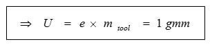
Unbalance, U (g mm)
Is a measure specifying how much unsymmetrical distributed mass deviates radially from the rotating axis; see image below.
U = m x e
Eccentricity, e (µm)
The distance between the rotational center and the center of gravity; see image below.
e = U / m
Unbalance force, F (N)
The unbalance creates a centrifugal force that increases linearly with the unbalance and is squared with the number of revolutions; see centrifugal force in the image below.
F = U x ω2
Tool balancing theory
- Rotating axis
- Center of gravity
- Eccentricity
- Unsymmetrical distributed mass
- Centrifugal force
Counterbalance
To compensate for unwanted centrifugal forces, it is possible to remove or add material that assists in directing the center of gravity to the rotating axis; see images below.
Unbalance
- Rotating axis
- Center of gravity
- Eccentricity
- Unsymmetrical distributed mass
Counterbalanced with drilled compensating hole
- Rotating axis
- Center of gravity
- Drill compensating hole
- Unsymmetrical distributed mass
Balance class according to ISO 1940-1 (G)
When balancing a tool according to ISO 1940-1 balancing class G 2.5 at 20 000 rpm, having an unbalance at 1 g mm/kg (e = 1 µm) is allowed; see chart below. As an example, a small Sandvik Coromant sticker corresponds to 4 g mm. The ISO 1940-1 standard allows for more unbalance on a heavier tool holder than on a lighter one at the very same rotational speed. This is allowed even though different unbalance creates different unbalance forces, whereby no consistent system load is achieved.
According to ISO 1940-1 – Balance quality requirements for rotors in a constant (rigid) state, G is a measure of the balancing quality of a rotating body. G is the tangential velocity at the center of gravity in relation to the rotational speed. G depends on the rotational speed (n), the body mass (m) and the unbalance (u). The G class is unidentified without knowing the rotational speed.
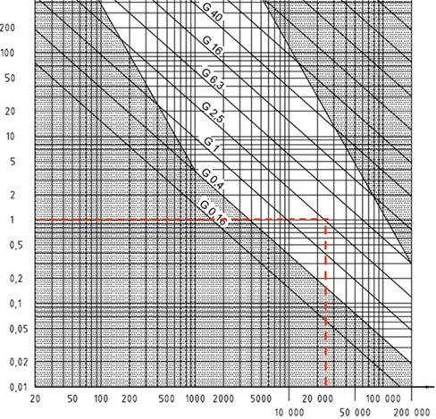
Permissible residual specific unbalance for different ISO 1940-1 G class levels
X-axis: Service speed n, rev/min
Y-axis: Permissible residual specific unbalance, eper, g mm/kg
Calculation example ISO 1940-1
Coromant Capto® C4 tool holder
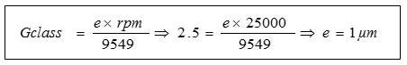
- Balance class: G2.5 at 20,000 rpm
- Tool mass: 1.0 kg
- Balance class equation
- Eccentricity = Unbalance/mass of tool
Sandvik Coromant sticker corresponds to 4 g mm
Balancing according to ISO 16084
A standard tailor-made for the application of high-speed cutting tools. The ISO 16084 standard means that the rotor tool system is balanced in a way that takes into account the actual load that the spindle bearings are subjected to. The standard does not use different G-classes, but instead gives a specific value for the accepted unbalance (U) for every tool in g mm.
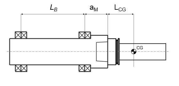
As the ISO 16084 is tailored just for the application of high-speed cutting tools, this also implies that a series of new parameters compared to the old ISO standard is introduced. This allows for a more realistic way to regulate the unbalance of the tool system. As mentioned, the unbalance requirements are derived from the amount of load that actually affects the bearings in the spindle, which is the basis for the entire standard. The fundamental equation for the ISO 16084 standard is as follows.
Step-by-step calculation guide
- Identify which spindle interface that applies (has individual defined parameters). E.g. Coromant Capto® C4 or HSK-A63
- Determine what kind of machining that is to be done
- Standard machining (fbal = 0.8)
- Fine machining (fbal = 0.2)
- Input specific parameters for the tool
- Tool mass (mt)
- Length to centre-of-gravity (Lcg)
- Rotational speed of the tool in RPM (n)
- Calculate the maximum allowed unbalance (USTAT,PER)
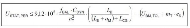
Calculation example ISO 16084
- Identify spindle interface: HSK-A63
- Cdyn = 25 000 N (maximum bearing load)
- Am = 50 mm (spindle nose bearing)
- Lb = 415 mm (length between bearings)
- Es = 2.00 µm (joining inaccuracy tool shank)
- Ubm,tol = 0.75 g.mm (tolerance of balancing machine)
- Machining determined: Fine machining, fbal = 0.2
- Specific parameters
- mt = 1.4 kg
- Rotational speed, n=3500 rpm
- Lcg = 75 mm
- USTAT,PER = 282 g.mm
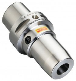
CoroChuck® 930
With the best pull-out security on the market, this chuck is designed to eliminate... chevron_right
Finish boring
Fine boring operations are performed to complete an existing hole and to achieve... chevron_right
Drilling
Drilling is often carried out late in the manufacturing process, after previous operations... chevron_right
Cylindrical Weldon Notch 9766 Temperature mm SE-811 81 Sandviken, Sweden <code>Balancing</code>... chevron_right
