
Finish boring
Fine boring operations are performed to complete an existing hole and to achieve a close hole tolerance and correct positioning with a high-quality surface finish. Machining is carried out with small cutting depths, generally below 0.5 mm (0.020 inch).
Single-edge boring is used for finishing operations with small cutting depths when close tolerance (IT6 to IT8) or a high-quality surface finish is required. The diameter of a fine boring tool can be adjusted within microns using a high-precision mechanism. Single-edge boring can be applied with a rough boring tool for finishing holes with tolerances of IT9 or larger.
Back boring
Back boring is used to enable the machining of a hole with a shoulder that cannot be reached from the opposite direction. Back boring can also be used to optimize the concentricity of a hole with a shoulder, since the entire hole is machined from only one position.
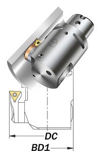
Note: Make sure the boring tool will go through the hole with the shoulder, and that the front of the boring tool will not collide with the component. When back boring, the boring tool is configured to go through a hole with a minimum diameter of Dc/2 + BD1/2.
Tool setting for back boring:
- Remove the grub screw from the top cutting fluid outlet and attach it into the lower cutting fluid outlet
- Adjust the fluid outlet in order to get the correct coolant position (for smallest tool sizes, the grub screw cannot be attached into the lower cutting fluid outlet)
- Rotate the cartridge 180°
- Use a slide extension if necessary
- Reverse the rotation direction
External boring
External finishing operations can be done with a fine boring tool in order to achieve a close diameter tolerance.
Tool setting for external boring:
- Reverse the rotation direction
- Reverse the head 180°
- Consider the maximum possible machining length, l3, and the outside diameter of the tool, to avoid collision
For external machining, the mass of the slide and fine boring head will rotate around the workpiece and cause high centrifugal forces. Therefore, maximum cutting speed for an external application must be calculated with respect to maximum cutting speed for the diameter when the head is rotated 180°, which means that the tool is configured for fine boring.
Calculation example:
- External diameter to be machined: 80 mm (3.15 inch)
- Internal diameter that could be machined (with this slide and head position): 210 mm (8.27 inch)
Note: Always add 130 mm (5.12 inch) to the diameter that should be machined to get the diameter to calculate maximum rpm. - Maximum cutting speed based on internal machining (in this example for CoroBore® 825): 1,200 m/min (3,937 ft/min)
- 1,200 m/min (3,937 ft/min) at diameter 210 mm (8.27 inch) is equal to 1,820 rpm. This means that 1,820 rpm is the maximum that could be used for this slide and head position
- For external machining, 1,820 rpm corresponds to cutting speed 460 m/min (1,509 ft/min) at diameter 80 mm (3.15 inch)
Choice of insert for finishing operations
Positive inserts are the First choice for all fine boring applications since they provide lower cutting forces than negative inserts. A large assortment of insert geometries is also available.
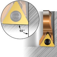
The entering angle for fine boring should be at least 90° (0° lead angle) in order to minimize the radial cutting forces and avoid vibration.
Most of Sandvik Coromant’s fine boring tools have an entering angle of 92° (-2° lead angle), to enable the machining of shoulders and blind holes without engaging the entire cutting edge.
Find out more about how to choose the correct turning insert.
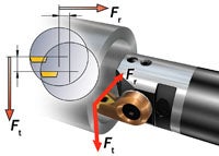
Cutting forces in finish boring
When the tool is in cut, a tangential and a radial component of the cutting force will attempt to deflect the tool away from the workpiece. The tangential component will try to force the tool downwards and away from the center line. In doing so, the tool clearance angle will be reduced.
Any radial deflection means that the cutting depth as well as the chip thickness is reduced, which can result in vibration tendencies.
Balancing in finish boring
Unbalance, caused by an asymmetrical tool or large run-out, generates a force that acts on the boring tool. In most applications, the force generated by unbalance is negligible compared to the cutting forces.
At high speeds, especially in long overhangs, the unbalance might cause vibration and will therefore influence the hole quality.
Tool deflection
The size of the tangential and radial components of the cutting force is affected by depth of cut, nose radius and entering angle.
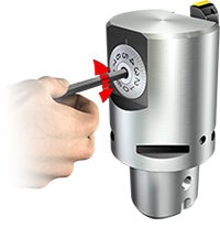
Deflection in radial direction affects the machined hole diameter. The tangential deflection affects the insert cutting edge by being deflected downwards, away from the center line. Follow our recommendations to compensate for radial deflections. Sandvik Coromant's fine boring tools are equipped with an adjustment mechanism that makes it possible to adjust the diameter within 2 μm (0.0787 μinch).
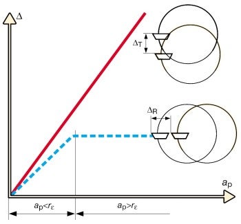
X-axis: Depth of cut
Y-axis: Deflection
Red line: Tangential deflection
Blue line: Radial deflection
Application checklist for fine boring
- Choose the largest possible coupling size or bar diameter
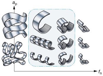
- Ensure proper chip control. Short/hard chips might cause vibrations and long chips might deteriorate surface finish or cause insert breakdown
- Choose the shortest possible overhang; use dampened boring bars for overhangs longer than four times the coupling size
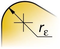
- A large insert nose radius (RE) will improve process security and surface finish but might generate vibrations. A nose radius larger than 0.4 mm (0.016 inch) is not recommended. A nose radius of 0.2 mm (0.008 inch) is recommended when using boring bars for small diameters
- Thin-coated or uncoated inserts normally provide lower cutting forces compared to thick-coated inserts. This is especially important when the relationship between tool length/diameter is large.
- A sharp cutting edge normally improves the hole quality by minimizing vibration tendencies
- A geometry with an open chip breaker can often be advantageous
- Choose a light cutting insert to generate good surface finish (not recommended for unstable conditions or long overhangs)
- Insufficient cutting edge engagement can increase vibration through friction during cutting
- Excessive cutting edge engagement (large depth of cut and/or feed) can increase vibration through tool deflection
- An insert grade with a higher level of toughness may be considered in some operations, as it could cope with any risks of chip jamming or vibration tendencies
- When producing close-tolerance holes, always ensure that final adjustment is made after measurement of the hole diameter while the tool is still in the machine spindle. This compensates for any misalignment between the pre-setter and the machine tool spindle, radial deflections or insert wear
- Make sure to clamp the boring tool and workpiece properly
- Use cutting fluid to improve chip evacuation, tool life and hole geometry
- Modular system for small diameters A conical shank will give a straighter hole at long overhangs, regardless of which chuck is used. A conical solid carbide shank should be chosen for overhangs up to 6 × DFor a cylindrical shank, the best straightness is generally given by short overhangsChoose heavy metal shanks for best stability and reduced vibration tendencies at short overhangsChoose high-precision hydraulic chucks for best stability and production security
See also How to apply boring for general recommendations.
See the handling instructions below for the recommended tightening torque.
Rough boring
Rough boring is primarily focused on metal removal and preparing the hole for finishing.... chevron_right
Boring
Boring is a machining process for enlarging or improving the quality of an existing... chevron_right
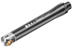
Fine boring tools
With our fine boring tools you can achieve close hole tolerances and a top-quality... chevron_right
How to apply boring
To achieve an optimized boring process, there are several factors to consider. Correct... chevron_right
