
Rough boring
Rough boring is primarily focused on metal removal and preparing the hole for finishing. Roughing machining is performed to open up an existing hole made by methods such as pre-machining, casting or forging. Rough boring tools can be configured for productive-, step- and single-edge boring.
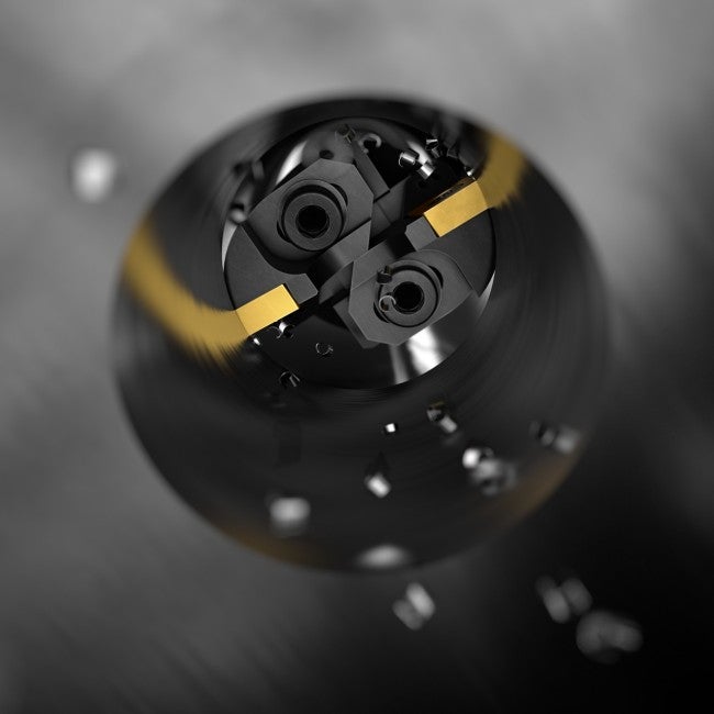
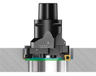
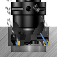
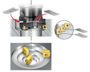
Productive boring
Productive boring is the basic set-up for most boring applications and is the best choice for highest productivity.
It involves two or three cutting edges and is employed for roughing operations of holes with tolerances of IT9 or larger, where metal removal rate is the first priority. Feed rate is obtained by multiplying the feed for each insert by the number of inserts (fn = fz × z).
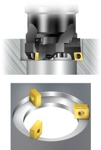
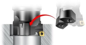
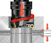
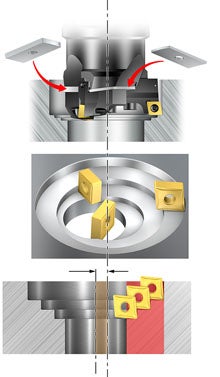
Step boring
A step-boring tool has the inserts set at different axial heights and diameters. This method is used when a large radial depth of cut is required or to get improved chip control in long-chipping materials, since the chips can be divided into smaller and easily handled chips. The number of tools and tool changes might be reduced when step boring.
The feed rate and produced surface finish is the same as if only one insert were used (fn = fz). The hole tolerance produced is IT9 or greater.
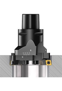
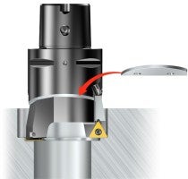
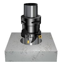
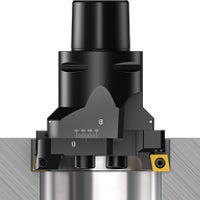
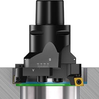
Single-edge boring
Single-edge boring is performed when using only one cutting edge. It can be beneficial in materials where chip control is demanding (e.g long-chipping materials), or when machine tool power is limited (fn = fz).
Choice of inserts for rough boring
Carefully select insert style, entering (lead) angle, geometry and grade to achieve good chip control and machining performance.
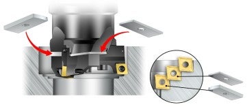
Positive or negative insert style
Negative inserts: Choose negative inserts in stable conditions for better insert economy and in tough applications that require strong inserts and improved process security.
Positive inserts: It is an advantage to use positive inserts in rough boring, as they produce lower cutting forces compared to negative inserts. A small nose angle and small nose radius also contribute to keeping the cutting forces down.
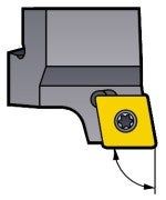
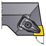
Entering/lead angle for rough boring
The entering angle (lead angle) of boring tools affects the direction and magnitude of axial and radial forces. A large entering angle (small lead angle) produces a high axial force, while a small entering angle (large lead angle) results in a high radial cutting force.
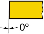
90° entering angle (0° lead angle)
First choice for general operations, step boring and shoulder operations.
84°/75° entering angle (6°/25° lead angle)
For interrupted cuts, sand inclusions, stack boring etc. Through holes only.
95° entering angle (-5° lead angle)
For high feeds or improved surface finish, with wiper inserts in stable conditions.
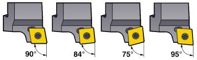
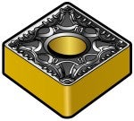
Positive inserts
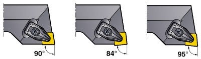
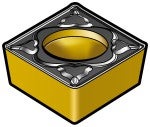
Negative inserts
Boring insert geometry and grade
Component material, type of operation and machining conditions define what insert geometry and grade to use. For boring, turning inserts are used. Find out more about how to choose the correct turning insert.
Recommendations
- Choose a roughing geometry for large cutting depths
- Choose a medium geometry for smaller cutting depths or to achieve improved chip breaking
- A large insert nose radius (RE) will improve process security and enable higher feed, but might generate vibration. The recommended starting nose radius is 0.08 mm (0.031 inch)
Machine considerations for rough boring
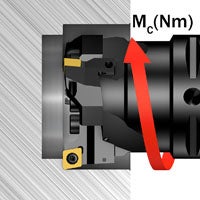
When rough machining, make sure the machine has the required power and torque needed for the specific boring application. Feed, number of inserts, hole diameter and depth of cut are the main affecting parameters.
Boring large diameter holes
Large diameter holes require greater torque than small diameter holes. Large diameter rough boring tools have larger inserts and can therefore handle larger depths of cut than small diameter tools. Make sure the machine has the required power and torque.
Boring blind holes
When machining a blind hole, it is very important to secure an efficient and correct chip evacuation.
- Correct cutting data is essential to achieve proper chip forming
- Ensure that the chips do not jam or wear the inserts
- Coolant pressure and flow should be sufficient to evacuate the chips
- Vertical machines are more critical than horizontal machines for efficient chip evacuation
Boring interrupted cuts
Machining interrupted cuts, such as cross holes, sets high demands on insert cutting conditions.
- Choose a tough grade
- Choose a strong, square negative basic-shaped insert for improved process security, valid for stable conditions
- Reduce cutting data if there are severe interruptions
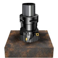
Boring sand inclusions – cast component
Sand inclusions in cast components increase wear on the inserts.
- Choose a tough grade
- Reduce cutting data
- Choose a strong square negative basic-shaped insert for improved process security and minimized wear
Boring gas-burned holes
Gas-burned holes could have local hardened areas that will generate more wear on the inserts.
- Choose a tough grade
- Reduce cutting data
- Choose a strong, square negative basic-shaped insert for improved process security and minimized wear
Large depth of cut in boring
If a really large depth of cut is needed, step-boring could be considered as a good alternative. Make sure the machine has the required power and torque.
Boring off-center holes
If the center lines of the pre-machined hole and the boring tool are not concentric, the cutting depth could be very large on one side of the hole. This could typically occur on cast components.
A good solution for these applications is step boring, in order to be able to handle the large depth of cut. Asymmetrical cutting forces might bend the tool and leave some off-center cutting or vibration, especially when long overhang tool assemblies are used.
Application checklist for rough boring
- Choose productive boring (triple-edge or twin-edge), step boring or single-edge boring
- Choose the largest possible coupling size
- Select the appropriate entering angle
- Ensure proper chip control. Short/hard chips might lead to vibration and long chips might deteriorate surface finish, causing insert breakdown
- Horizontal machining and cutting fluid improve chip evacuation in blind holes
- Select insert geometry and grade:
- Choose the shortest possible overhang; use dampened boring bars for overhangs longer than four times the coupling size
- Select appropriate cutting data and consider overhang.
Note: Do not use the maximum recommended feed and cutting depth at the same time. The maximum recommended starting speed is 200 m/min (656 ft/min) to ensure proper chip evacuation - A large insert nose radius (RE) will improve process security and enable higher feed, but might generate vibration. The recommended starting nose radius is 0.8 mm (0.031 inch)
- Use positive inserts, as they provide lower cutting forces compared to negative inserts
- Choose negative inserts in stable conditions for better insert economy and in tough applications that require strong inserts and improved process security
- Insufficient cutting edge engagement can increase vibration through friction during cutting
- Rigid clamping with face contact to the spindle improves stability
- Excessive cutting edge engagement (large depth of cut and/or feed) can increase vibration
- Make sure the machine can provide the required torque and power for the specific boring application
- Wiper inserts can be used to improve surface finish or increase feed, but are not recommended for unstable conditions and long overhangs
- Make sure to get proper clamping for the boring tool and workpiece
- Use cutting fluid to improve chip evacuation, tool life and hole geometry
- For the best performance of multi-edge boring tools, it is recommended to machine in the higher area of the cutting depth and feed recommendations, especially for longer overhangs. Note: Do not use the maximum cutting depth and feed at the same time
- Productive boring machining enables the maximum penetration rate. If a very large depth of cut is needed, it could be more productive to opt for step boring, since the cycle time can be minimized and fewer tools may be needed
See also How to apply boring for general recommendations.
See the handling instructions below for the recommended tightening torque.
Boring
Boring is a machining process for enlarging or improving the quality of an existing... chevron_right
Finish boring
Fine boring operations are performed to complete an existing hole and to achieve... chevron_right
Boring
In this section, you will find boring formulas and definitions needed for your boring... chevron_right
Silent Tools™ for boring
Problems that originate from vibration are frequently encountered in boring and other... chevron_right
