
Coolant aspects – Machining with coolant
In some cases, it may be beneficial, from environmental and cost perspectives, to machine without coolant (dry machining). However, many applications require machining with coolant for tolerance, surface quality and machinability. If coolant is required, it should be optimized to maximize its true potential.
High-pressure coolant
Nearly all machines offer a standard high-pressure coolant capability of 70/80 bar (1015/1160 psi). Some machines can even deliver higher coolant pressures, up to 150 bar (2176 psi), for demanding operations and materials.
The benefits can be great for both turning and drilling operations; however, it is worth noting:
- Benefits will only be achieved with tools developed for precision coolant applications, i.e. drills with through coolant and turning tools with targeted jets
- The required coolant pressure to break the chip for turning tools depends on the nozzle delivery design, material being machined and the depth of cut and feed
- The coolant flow required depends on the pressure and the total coolant delivery area of the tool channels
Select the right tools and pump (pressure and flow) for each application. A correctly applied high-pressure coolant system will provide quick payback, due to increased machine utilization and increased metal-cutting efficiency.
Benefits when machining with coolant
Combining high pressure with optimized cutting tools and quick change has many benefits.
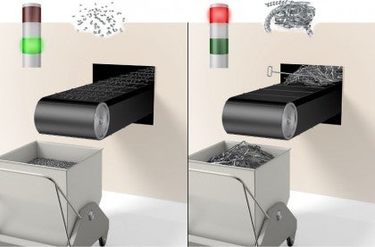
Chip control
Eliminate two of the biggest production time killers when the red light is on.
- Machine stoppages: Long chips gathering around the tool or component
- Service: Chips "bailed" in the chip conveyor put the machine out of action for hours or days
Chip evacuation in drilling

Internal through coolant helps with chip evacuation, preventing chip jamming in the flute.
Fixed nozzle position
No need for operator settings, which means increased machine utilization.
Increased cutting speed
Results in higher metal-cutting efficiency.
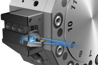
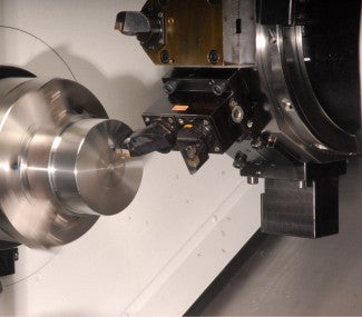
Precision coolant with high pressure
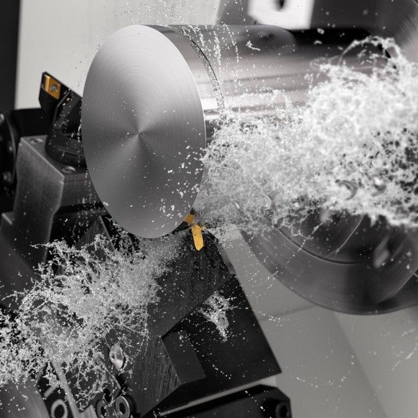
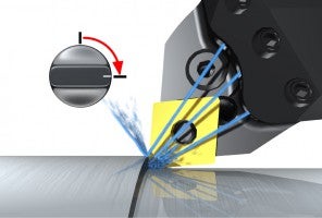
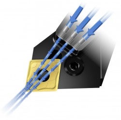
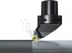
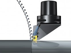
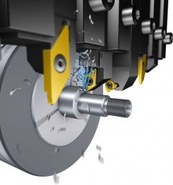
High pressure in the machine, together with modern turning tools that feature nozzles, can produce a high-velocity coolant jet. The coolant jets are directed toward the cutting zone on the insert rake side and act as a hydraulic wedge to lift the chips. This shortens the contact length between the insert and the material, which helps to reduce cutting forces, lower the temperature and improve chip control.
High-pressure coolant principles
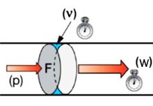
Pressure (p): Force per unit area
- Pascal, N/m
- Bar (1 bar = 0.1 MPa)
- psi, pounds/in2 (1 bar = 14.5 psi)
Low rate (v): Volume displaced per time unit, liter/min (gallon/min)
Velocity (w): Speed at which the fluid moves through a tube, m/s (ft/s)
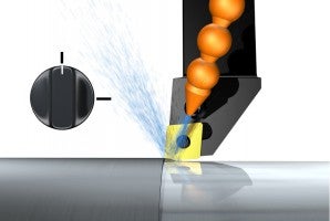
Reducing the delivery area increases the velocity of the jet and at the same time reduces the flow for a given pressure. Utilizing optimized small-diameter nozzles produces an accurate laminar jet.
Flow velocity w1

Flow velocity w1
w2>>w1

In the diagram below, the volume flow required is shown in relation to the nozzle diameter for a fixed 80 bar (1160 psi) pressure. By using small diameter nozzles, high-velocity jets can be produced, while at the same time reducing the flow and energy required compared to traditional coolant systems.
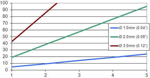
X-axis: Number of nozzles
Y-axis: Flow, liters/min
Pump requirements
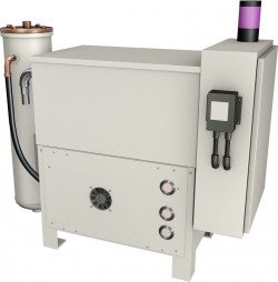
The pump requirements for successfully applying high-pressure coolant concern pressure and flow.
Pressure
The pressure requirement for breaking chips varies depending on the material and the cutting parameters. 80 bars (1160 psi) is adequate for most applications. Higher pressures, up to 150 bar (2176 psi), are used for hard-to-break chips in materials such as Inconel and Super Duplex
Flow
The flow required is driven by the number and diameter of coolant outlets.
- Use a 20 micron filter
- Turning: If using tool holders with three 1 mm (0.039 inch) coolant nozzles, the flow requirement is 20 liters/min per tool position. However, it is important to consider the number of tools being run with coolant at the same time (number of tools x 20 liters/min). Because of the size of the machine, a large tank is needed to provide time for circulation
- Drilling: The coolant hole diameters in the drill increase with the drill diameter, meaning that a higher flow rate is needed for larger diameter drills. The goal is volume of flow, not pressure. A variable pressure pump is recommended, as well as using lower pressures with larger diameter drills
| Drill diameter | 20 l/min | 40 l/min |
| 12 | 70 bar | 70 bar |
| 20 | 30 bar | 70 bar |
| 25 | 12 bar | 50 bar |
| 30 | 6 bar | 23 bar |
| 40 | 1 bar | 3 bar |
| 60 | | 1 bar |
Coolant connection

One of the main benefits of using high-pressure coolant systems is the reduction of coolant pipe setting. With external pipes, it normally takes two to three attempts to get the coolant position right. Poor chip control often knocks the pipe and resetting is quite a regular occurrence, meaning that the process is inconsistent and the red light is on.
When using tool holders with precision nozzles, the coolant delivery from the tool to the cutting edge is fixed, but the coolant still needs to be connected to the tool holder. Pipe connections to a shank holder can be used; however, this will increase the set-up time every time the tool is changed, as well as interference, in addition to creating a chip trap.
The best solution is to use quick change, a plug-and-play solution. The coolant is permanently plumbed into the tool holder clamping unit. With these solutions, the adoption of machining with high-pressure coolant has the additional benefit of reduced set-up times, on top of chip control and increased metal-cutting efficiency.
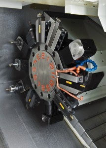
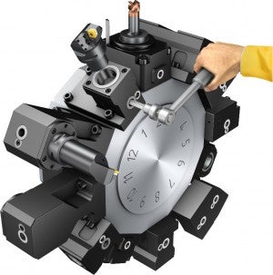
Coolant connection in turning centers and lathes
With Coromant Capto® clamping units, the coolant is plumbed through the turret, allowing for quick change and pre-measuring outside the machine. Clamping units are available for all lathe styles (turning centers, vertical lathes and flatbed lathes) and new clamping sets allow for a pressure of 200 bars (2900 psi).
Coolant connection in sliding head machines
Coolant delivery on a sliding head machine varies considerably compared to a turning center. Synthetic oil is used, rather than emulsion, to support the sliding guide way construction and the oil is delivered to all tools simultaneously regardless of which tool is in cut.
Although most machines are delivered with high-pressure pumps, without optimized tooling, the coolant delivery area (diameter of coolant outlet x number of outlets) will probably be too large for the flow capability of the pump, so maximum pressure will not be achieved.
It is important to reduce the delivery area by:
- Using tools with internal coolant supply and blocking off external supply to these tools
- Optimizing the coolant delivery area to minimize the flow required
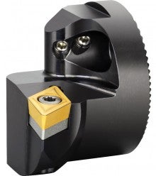
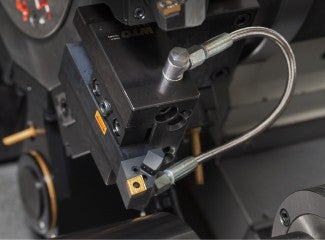
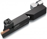
The QS™ holding system includes tool holders that have the coolant plumbed into the stop, which is permanently mounted in the machine. A coolant tube in the back of the QS™ tool holder ensures that the coolant is channeled straight out to the nozzles at the same time that the tool is mounted.
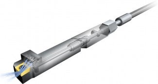
The nozzles are 1 mm (0.039 inch) in diameter, ensuring an accurate jet to assist chip control while at the same time keeping the flow requirement to a minimum.


Sleeves for quick set-up of boring bars
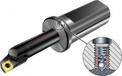
High-pressure metallic sealed sleeves such as EasyFix provide quick set-up of cylindrical shank boring bars. The spring-loaded ball locates the groove in the boring bar to find the center position in seconds.
How to apply coolant and cutting fluid in turning
The primary functions of cutting fluid are chip evacuation, cooling, and lubrication... chevron_right
Machining centers
Machining centers satisfy all demands for components and operations such as milling,... chevron_right
Multi-task machines – Vertical
The primary benefit of a multi-task machine is that you can combine several cutting... chevron_right
Parting and grooving
In parting and grooving, process security and productivity are two important aspects.... chevron_right
