
How to choose thread turning insert and shim
When choosing the most suitable thread turning insert for your application you need to consider the insert type, flank/radial clearance and the insert geometry. These are all factors that influences chip control, insert wear, tool life and thread quality.
How to choose insert type
When turning a thread, there are three main insert types to choose between; full profile, V-profile and multi-point inserts. Each type has its advantages and disadvantages.
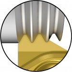
Full profile insert
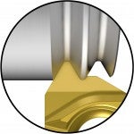
The full profile insert is the most common insert type. It is used to cut a complete thread profile, including the crest.
Advantages
- Ensures correct depth, bottom and top profile for a stronger thread
- No deburring of the thread profile needed
- Fewer passes required compared to a V-profile insert, thanks to the larger nose radius
- Gives a productive threading performance.
Disadvantage
A separate insert is required for each pitch and profile.
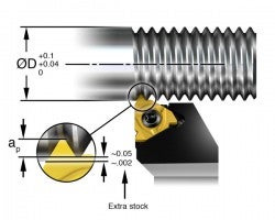
Note! Extra stock /material should be left on the workpiece for topping the finish diameter of the thread (0.05–0.07 mm (0.002–0.003 inch)).
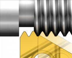
V-profile insert
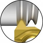
V-profile inserts do not top the thread crests. Therefore, the outer diameter for screws and inner diameter for nuts must be turned to the right diameter prior to threading.
Advantages
- Flexibility; the same insert can be used for a range of pitches, provided that the thread profile angle (60° or 55°) and radius are the same
- Minimum tool inventory needed
Disadvantages
- The insert nose radius is smaller to cover the range of pitches, which reduces tool life
- Burr formation can be a problem
Multi-point insert
Multi-point inserts are similar to full profile inserts, but have more than one insert point (NT>1). A two-pointed insert doubles the productivity and a three-pointed insert triples the productivity, etc.
Advantages
- Requires fewer passes, which gives better tool life, productivity and lower tool costs
Disadvantages
- Stable conditions are needed due to increased cutting forces as the cutting edge has a longer contact length
- Needs sufficient room behind the last thread to clear the last tooth of the insert, generating a full thread depth
How to choose insert geometry
Selecting the correct insert geometry is important when thread turning. The geometry influences chip control, insert wear, thread quality and tool life.
Flat geometry
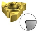
- All-round, can be used for most materials
- Edge rounded cutting edge for edge strength
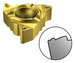
Sharp geometry

- For sticky or work-hardening materials, e.g. low-carbon steel, stainless steel, non-ferrous materials and super alloys
- Sharp cutting edge for low cutting forces and good surface finish
Chip-breaking geometry
- For long-chipping materials, e.g. low-carbon materials. Can also be used for stainless steel, alloyed steel and non-ferrous materials
- Chip-forming geometry that enables a more continuous and unsupervised machining
- Not to be used with radial infeed
Read more about threading inserts and grades
Insert clearance angles
Angular clearance between the insert and thread is necessary for precise, accurate thread turning. There are two types, radial clearance (ALP) and flank clearance (ALF).
 | |||
| Radial clearance | Flank clearance |
Flank clearance
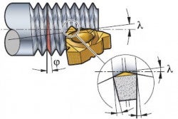
Cutting edge clearance between the sides of the insert and thread flank is essential to ensure even tool wear and consistent, high quality threads. The insert should therefore be tilted to gain maximum symmetrical clearance from the flanks (flank clearance angle) and to get the correct thread profile. The tilt angle of the insert should be the same as the helix of the thread.
Flank clearance
Selection of shim
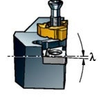
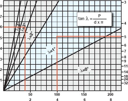
Insert shims are used to give different tilts to the insert, so that the angle of insert inclination (λ) is the same as the helix of the thread. See table below for methods on how to select the correct insert shim.
- The standard shim in many holders is 1° which is the most common angle of inclination
- Negative shims are used when turning left-hand threads with right-hand tools and vice versa
| Lead (Pitch) mm | Threads/inch | ||
 | |||
| Workpiece diameter | mm inch |
Example:
- Pitch=6 mm and workpiece= Ø40 m: a 3° shim is required
- Pitch=5 threads per inch and workpiece= Ø4 inches: a 1° shim is required
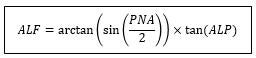
Threads with small profile angles
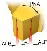
ALP = Radial clearance
ALF = Flank clearance
For ACME, trapezoidal and rounded threads it is especially important to choose the correct shim to tilt the insert, because the pressure on the cutting edge is higher and the flank clearance is smaller.
Flank clearance (ALF) depending on profile
| Flank clearance (ALF) | Flank clearance (ALF) | ||
| Metric, UN | 60° | 7.6° | 5° |
| Whitworth | 55° | 7.1° | 4.7° |
| Trapezoidal | 30° | 4° | 2.6° |
| ACME | 29° | 3.8° | 2.5° |
| Buttress | 10°/3° | 2.7°/0.8° | 1.8°/0.5° |
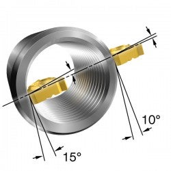
Radial clearance
To set the correct radial clearance, the inserts are tilted 10° or 15° in the tool holder. It is important to use internal inserts with internal tool holders, and vice-versa, to ensure that the correct thread form is achieved.
Insert sizes:
11, 16 and 22 mm
(1/4, 3/8 and 1/2 inch)

Insert size:
27 mm (5/8 inch)
