Thread milling application tips
To achieve the best results in thread milling operations, always consider the following recommendations.
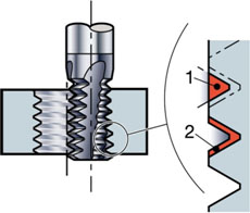
Choice of cutting diameter
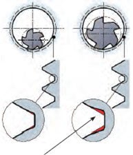
A smaller cutting diameter will help to achieve higher quality threads. The cutter engagement will create a minute form error on the root of the thread profile. In internal thread milling applications, the relationship between threading diameter, cutting diameter and pitch will affect the true radial depth of cut, ae eff, which becomes much larger than the chosen radial depth of cut. A larger true ae will increase the deviation in the root of the thread. To minimize the profile deviation, the cutter diameter should be no greater than 70% of the threading diameter.
Example M30x3
A tool of 21.7 mm diameter gives a profile deviation of 0.07 mm (0.0027 inch).
A tool of 11.7 mm diameter gives a profile deviation of 0.01 mm (0.0004 inch).
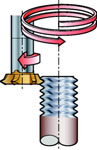
Thread milling tool path
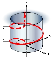
Thread milling tool path will give right or left hand threads, using down-milling or up-milling. Always engage and retract the thread mill in a smooth path, i.e. roll in and out of cut. Thread milling requires machine tools which are capable of simultaneous movements on the X, Y and Z axes. The thread diameter is determined by the X and Y axis, while pitch is controlled by the Z axis.
| Pitch |
|
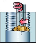
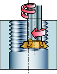
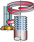
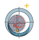
Right-hand internal threads
All cutters are initially positioned as close as possible to the bottom of the hole, and then move anticlockwise in an upwards direction to ensure that down-milling is achieved.
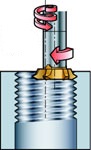
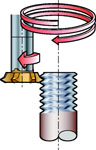
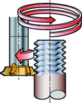
Left-hand internal threads
Milling a left-hand thread follows in the opposite direction, from top to bottom, also in an anticlockwise path to ensure that down-milling is achieved.
| Internal | |
|---|---|
| Right-hand threads | Left-hand threads |
| Down-milling | |
|
|
| Up-milling | |
|
|
| External | |
|---|---|
| Right-hand threads | Left-hand threads |
| Down-milling | |
|
|
| Up-milling | |
|
|
Down-milling
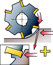
- Down-milling is when the tool is fed in the direction of tool rotation
- Down-milling is always the preferred method - when machine tool, fixture and workpiece will allow
- Chip thickness decreases from the start of cut, until reaching zero at the end, which stops the edge rubbing and burning against the surface before it is engaged into cut
Up-milling
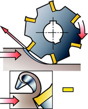
- In up-milling, the feed direction of the cutting tool is opposite to its rotation
- The cutting edge has to be forced into the cut, creating a rubbing or burnishing effect with friction, high temperatures and often contact with a work-hardened surface caused by the preceding edge. All this shortens tool life
- Thick chips on exit from cut will reduce tool life
- The large thickness and higher temperature at exit will sometimes stick or weld the chips to the cutting edge and carry them around to the start of the next cut or cause edge frittering momentarily
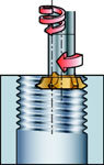
Entrance into cut – roll in
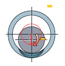
Make a soft entrance into the cut when circular milling or circular ramping. This can be done by performing an extra circle, which results in slow engagement into the material. For each quarter revolution (90°) during the entrance into cut, the pitch should be divided by four. Smooth entrances into the cut are essential to avoid vibration and extend tool life.
Feed per tooth
Always work with small feed per tooth values to achieve best quality and to avoid feed marks on the component surface. Feed per tooth should not exceed 0.15 mm/tooth (0.006 inch/tooth), therefore a small hex value is needed.
Feed required by the machine software
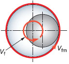
Always calculate the correct thread milling feed rates required by machine software to ensure the correct insert load. The feed always depends on the hex value which corresponds with the peripheral feed rate. However, many machines require a tool centre feed (vf). In internal thread milling applications, the tool path of the periphery is faster than the movement of the tool centre line. Feed rate programming on most milling machines is based on the centre line of the spindle and this must be included in thread milling calculations to maximize tool life and avoid vibration/tool breakdown.
Number of passes
Separating the thread milling operation into several passes achieves larger thread pitches and improves security against tool breakage in difficult materials. Thread milling with several passes also improves thread tolerance due to reduced tool deflection. This gives greater security in long overhangs and unstable conditions. Always use two or more passes when thread milling in hardened and difficult materials.
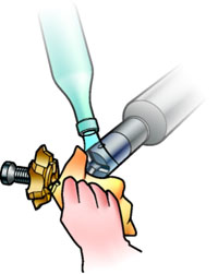
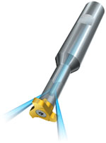
Dry or wet machining
Dry machining is always recommended as cutting fluid emphasizes temperature variations at entry and exit, creating thermal cracks. Cutting fluid can be beneficial on certain occasions, such as when finishing stainless steels/aluminium, machining HRSA or machining cast iron (to reduce toxic dust). However, it is most beneficial to evacuate chips using compressed air.
Cutting data considerations
- In internal thread milling applications, ae is increased relative to straight cutting, which reduces the chip thinning effect
- In external thread milling applications, the radial depth becomes much smaller and a higher cutting speed can be used
- The entering angle for the nose radius is 90°. Since this is the most sensitive part of the insert, hex calculations should be made using an entering angle of 90°
For cutting data and values, use the CoroPlus® ToolGuide
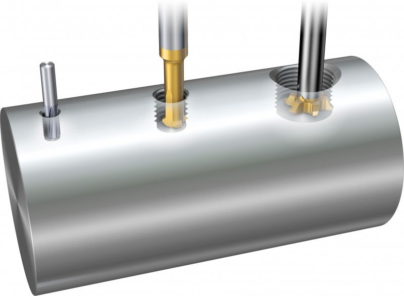
Thread milling hole sizes
Thread mills use the same hole sizes as for tapping. Always look for as big a hole as possible without going outside the tolerance. This will ensure a safer process and a longer tool life. When using a full profile insert, a smaller hole is required to ensure a machined top of thread.
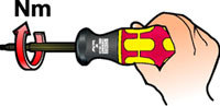
Handling
To get the best performance out of tool holders that have screw clamped inserts, always use a torque wrench to ensure the insert will be securely seated.
- A torque set too high will affect the performance of the tool negatively and cause insert and screw breakage
- A torque set too low will cause vibrations and inaccurate cutting results
- Change the insert screw regularly and make sure the tip seat is clean and free from obstructions that could offset the insert. These checks are essential for the reliability of the thread milling process