
Drilling formulas and definitions

Find the cutting tool for your specific task and get instant cutting data recommendations.
Go to CoroPlus® ToolGuide
Drilling formulas
To know how to calculate drilling speeds and feeds is critical for successful drilling. In this section you find the drilling formulas and definitions needed for your drilling operations, such as cutting speed, feed per revolution and specific cutting force.
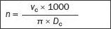
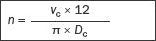
| Cutting speed, (vc) m/min | Cutting speed, (vc) ft/min |
 |  |
| Spindle speed,(n)rpm | Spindle speed,(n)rpm |
 |  |
| Penetration rate, (vf) mm/min | Penetration rate, (vf) inch/min |
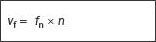 | |
| Feed per revolution, (fn) mm/rev | Feed per revolution, (fn) inch/rev |
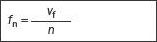 | |
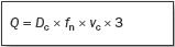
| Metal removal rate, (Q) cm3/min | Metal removal rate, (Q) inch3/min |
 |  |
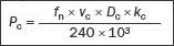
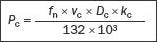
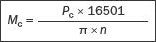
| Net power, (Pc) kW | Net power, (Pc) HP |
 |  |
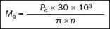
| Torque, lbf Nm | Torque, lbf ft |
 |  |
| Specific cutting force, (kc) N/mm | Specific cutting force, (kc) ibf/inch |
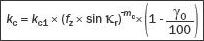 | |
| Feed force, (Ff) N | Feed force, (Ff) ft/min |
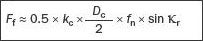 | |
| Machining time, (Tc) min | Machining time, (Tc) min |
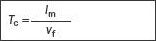 | |
Drilling definitions
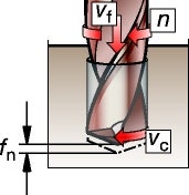
Penetration rate
Productivity in drilling is strongly related to the penetration rate,vf.
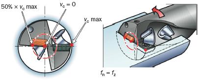
Cutting speed for indexable drills
– one central and one peripheral insert
The cutting speed declines from 100% at the periphery to zero at centre. The central insert operates from cutting speed zero to approximately 50% of vc max, The peripheral insert works from 50% of vc max. up to 100% of vc max.
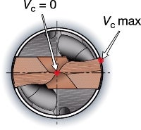
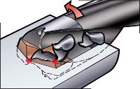
Cutting speed for solid carbide drills and exchangeable tip drills
Two edges from the centre to the periphery.
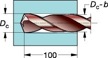
Back taper
A solid or brazed carbide drill is ground slightly tapered on its outer diameter supply clearance, which prevents the drill from jamming in the hole.
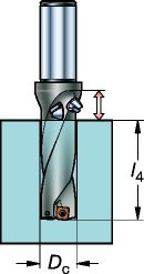
Hole depth
l4 is the maximum recommended hole depth.
How to calculate tool life
Tool life (TL) can be measured using distance, in meters, number of holes, or in minutes.
Tool life calculation - theoretical example:
Dc 20 mm, vc = 200 m/min, n = 3184 rpm, fn = 0.20 mm/r, hole depth = 50 mm
TL (meters): 15 meters
TL (No. of holes): 15 x 1000/50 = 300 holes
TL (min): 15 x 1000/vf = 15 x 1000/(fn x n)
= 15 x 1000 / (0.20 x 3184) = 23 min
The most common tool life criteria in drilling is flank wear. Tool life is dependent on:
- Cutting data
- Carbide grade and insert geometry
- Workpiece material
- Diameter (a small diameter drill travels a longer distance in a shorter time)
- Hole depths (many short holes means many entries/exits which decrease tool life).
- Stability
