Milling formulas and definitions

Find the cutting tool for your specific task and
get instant cutting data recommendations.
Here you find a collection of good to have milling formulas and definitions that are used when it comes to the milling process, milling cutters, milling techniques and more. Knowing how to calculate correct cutting speed, feed per tooth or metal removal rate is crucial for good results in any milling operation.
f Table feed, v (mm/min) | f Table feed, v (inch/min) |
 |  |
c Cutting speed, v(m/min) | c Cutting speed, v (ft/min) |
 |  |
| Spindle speed, n (r/min) | Spindle speed, n (rpm) |
 |  |
z Feed per tooth, f(mm) | z Feed per tooth, f (inch) |
 |  |
n Feed per revolution, f (mm/rev) | n Feed per revolution, f (inch/rev) |
 |  |
3 Metal removal rate, Q (cm/min) | 3 Metal removal rate, Q (inch/min) |
 |  |
c Net power, P (kW) | c Net power, P (HP) |
 |  |
c Torque, M(Nm) | c Torque, M(lbf ft) |
 |  |
| Symbol | Designation/definition | Metric | Imperial |
| ae | Radial depth of cut | mm | inch |
| ap | Axial depth of cut | mm | inch |
| DCap | Cutting diameter at cutting depth ap | mm | inch |
| Dm | Machined diameter (component diameter) | mm | inch |
| fz | Feed per tooth | mm | inch |
| fn | Feed per revolution | mm/r | inch |
| n | Spindle speed | rpm | rpm |
| vc | Cutting speed | m/min | ft/min |
| ve | Effective cutting speed | mm/min | inch/min |
| vf | Table feed | mm/min | inch/min |
| zc | Number of effective teeth | pcs | pcs |
| hex | Maximum chip thickness | mm | inch |
| hm | Average chip thickness | mm | inch |
| kc | Specific cutting force | N/mm2 | N/inch2 |
| Pc | Net power | kW | HP |
| Mc | Torque | Nm | lbf ft |
| Q | Metal removal rate | cm3/min | inch3/min |
| KAPR | Entering angle | degree | |
| PSIR | Lead angle | degree | |
| BD | Body diameter | mm | inch |
| DC | Cutting diameter | mm | inch |
| LU | Usable length | mm | inch |
The milling process – definitions
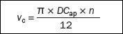
Cutting speed,vc
Indicates the surface speed at which the cutting edge machines the workpiece.
Effective or true cutting speed, ve
Indicates the surface speed at the effective diameter (DCap). This value is necessary for determining the true cutting data at the actual depth of cut (ap). This is a particularly important value when using round insert cutters, ball nose end mills and all cutters with larger corner radii, as well as cutters with an entering angle smaller than 90 degrees.
Spindle speed, n
The number of revolutions the milling tool makes per minute on the spindle. This is a machine oriented value, which is calculated from the recommended cutting speed value for an operation.
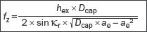
Feed per tooth, fz
A value for calculating the table feed. The feed per tooth value is calculated from the recommended maximum chip thickness value.
Feed per revolution, fn
Auxiliary value indicating how far the tool moves during one complete rotation. It is used specifically for feed calculations and often to determine the finishing capability of a cutter.
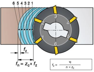
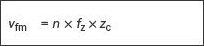
Feed per minute, vf
Also known as the table feed, machine feed or feed speed. It is the feed of the tool in relation to the workpiece in distance per time-unit related to feed per tooth and number of teeth in the cutter. The number of available cutter teeth in the tool (zn) varies considerably and is used to determine the table feed while the effective number of teeth (zc) is the number of effective teeth in cut. Feed per revolution (fn) in mm/rev (inch/rev) is a value used specifically for feed calculations and often to determine the finishing capability of a cutter.
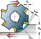
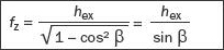
Maximum chip thickness, hex
This value is a result of the cutter engagement as it is related to (fz), (ae) and (kr). The chip thickness is an important consideration when deciding the feed per tooth, to ensure that the most productive table feed is employed.
Average chip thickness, hm
A useful value in determining the specific cutting force, used for net power calculations.
Metal removal rate, Q (cm3/min)
The volume of metal removed in cubic mm per minute (inch3/minute). It is established using the values for cutting depth, width and feed.
Specific cutting force, kct
A material constant which is a factor used for power calculations, expressed in N/mm2
Machining time, Tc (min)
Machining length (lm) divided by the table feed (vf).
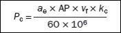
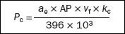
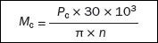
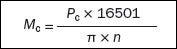
Net power, Pc and efficiency, ηmt
Machine tool oriented values, which assist in calculating the net power to ensure that the machine can handle the cutter and operation.
Milling techniques – definitions
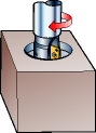
Linear ramping
A simultaneous straight movement in axial and radial feed directions.
Circular milling
A circular tool path on a constant z-level (circular interpolation).
Circular ramping
A circular ramping tool path (helical interpolation).
Waterline milling
Milling on a constant z-level.
Point milling
A shallow radial cut with round insert or ball nose cutters in which the cutting zone is moved away from the tool centre.
Scallop
A configuration with cusps that occurs when producing sculptured surfaces.
Specific milling cutter formulas
Formulas for milling cutters having a straight cutting edge
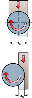
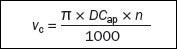
Max. cutting diameter at a specific depth (mm).
Face milling (centred workpiece), straight edge and side milling (ae > Dcap/2) mm

Side milling (ae < Dcap/2) straight edge mm.
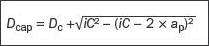
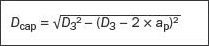
Formulas for milling cutters with round inserts
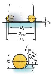
Max. cutting diameter at a specific depth (mm).
Face milling round insert (ae > Dcap/2) (mm)

Side milling (ae < Dcap/2) and round insert (ap < iC/2) mm.
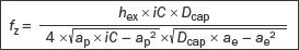
Ball nose end mills
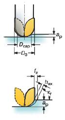
Max. cutting diameter at a specific depth (mm).
Feed per tooth (mm/tooth), cutter centered.

Feed per tooth (mm/tooth), side milling
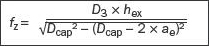
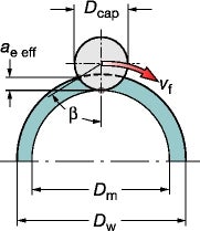
Internal circular ramping (3-axes) or circular milling (2-axes)
Calculated version
Peripheral feed (mm/min)
Tool centre feed (mm/min)

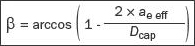
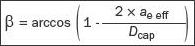
Radial depth of cut (mm)

In a solid workpiece where Dw = 0 and ae eff = Dm/2
Feed per tooth (mm)

When widening a hole,
Feed per tooth (mm)
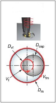
Circular ramping in solid workpiece
Circular ramping or circular milling to widen a hole.
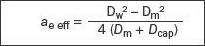
Circular milling with a roll into cut tool path, Dvf1
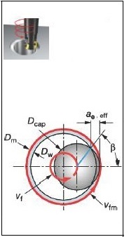
Formulas for external circular ramping (3-axes) or circular milling (2-axes)
Calculated version
Peripheral feed (mm/min)

Tool centre feed (mm/min)

Feed per tooth (mm)

Milling insert definitions
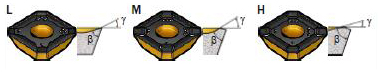
Insert geometry
A closer study of the cutting edge geometry reveals two important angles on the insert:
-
rake angle (γ)
-
cutting edge angle (β)
The macro geometry is developed for work under light, medium or heavy conditions.
-
L (Light) geometry has a more positive, but weaker edge (large γ, small β)
-
H (Heavy) geometry has a stronger, but less positive edge (small γ, large β)
The macro geometry affects many parameters in the cutting process. An insert with a strong cutting edge can work at higher loads, but also generates higher cutting forces, consumes more power and generates more heat. Material optimized geometries are designated with the ISO classification letter. For example, geometries for cast iron: -KL, -KM and -KH.
| | Geometry | | |
|---|---|---|---|
| Parameter | L | M | H |
| Edge strength | Low | Medium | High |
| Cutting forces | |||
| Power consumption | |||
| Max. chip thickness | |||
| Heat generated |
Insert corner design
The most important part of the cutting edge for producing the surface is the parallel land bs1 or, when applicable, a convex wiper land bs2, or corner radius, rε.
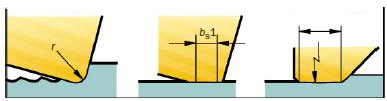
Corner radius, r Parallel land (bs1)Wiper land (bs2)
Milling cutter definitions
Entering angle, (kr) (degrees)
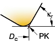
The major cutting edge angle (kr) of the cutter is the dominant factor as it affects the cutting force direction and the chip thickness.
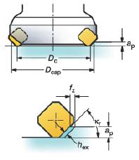
Cutter diameter – Dc (mm)
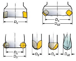
The cutter diameter (Dc) is measured over the point (PK), where the main cutting edge meets the parallel land.
The most important diameter to consider is (Dcap) – the effective cutting diameter at the actual depth of cut (ap) – used for calculation of the true cutting speed. D3 is the largest diameter of the insert, for some cutters it is equal to Dc.
Cutting depth – ap (mm)
The cutting depth (ap) is the difference between the uncut and the cut surface in axial direction. Maximum ap is primarily limited by the insert size and machine power.
Another critical factor in roughing operations is torque, and in finishing operations, it is vibration.
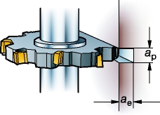
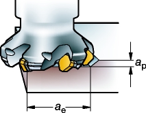
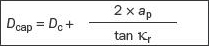
Cutting width, ae (mm)
The radial width of the cutter (ae) engaged in cut. Especially critical in plunging step over, and for vibration in corner milling, where maximum ae is especially critical.
Radial immersion, ae/Dc
Radial immersion (ae / Dc) is the width of the cut in relation to the diameter of the cutter.
Number of effective cutting edges on the tool, zc
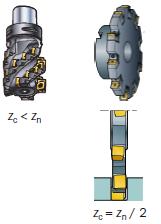
For determining the table feed (vf) and the productivity. This often has a critical influence on chip evacuation and operational stability.
The total number of cutting edges on the tool, zn
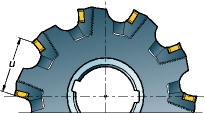
Distance between the effective cutting edges, u
For a specific milling cutter diameter, you can choose between different pitches: coarse (-L), close (-M), extra close (- H). An X added to the code, denotes a cutter version whose pitch is slightly closer than its basic design.
Differential pitch
Indicates an unequal space between the teeth on a cutter. This is a very effective way to minimize vibration tendencies.