Threading formulas and definitions
This section covers threading formulas and definitions for how to calculate cutting speed, feed rate or any other parameter for your thread turning, thread milling or tapping operations. You also find the designation for different thread forms according to international standards.
Thread turning formulas and definitions
Infeed
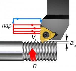
By dividing the full cutting depth of the thread into smaller cuts, the sensitive nose radius of the insert is not overloaded.
Example: By taking 0.23–0.10 mm (0.009–0.004 inch) in cutting depth per pass (radial infeed), the full cutting depth (ap), and the profile depth of the thread (0.94 mm (0.037 inch)), is turned on a 1.5 mm (0.06 inch) pitch metric thread in 6 passes (nap).

1st pass, infeed
0.23 mm

= 0.009 inch

2nd pass, infeed
0.42–0.23 = 0.19 mm

0.017–0.009 = 0.008 inch

3rd pass, infeed
0.59–0.42 = 0.17 mm

0.023–0.017 = 0.006 inch

4th pass, infeed
0.73–0.59 = 0.14 mm

0.029–0.023 = 0.006 inch

5th pass, infeed
0.84–0.73 = 0.11 mm

0.033–0.029 = 0.004 inch

6th pass, infeed
0.94–0.84 = 0.10 mm

0.037-0.033 = 0.004 inch

The infeed can be calculated according to the formula:
Δap = Radial infeed, cutting depth per pass
X = Actual pass (in a series from 1 to nap)
ap = Total depth of thread + extra stock
nap = Number of passes
Y = 1st pass = 0.3
2nd pass = 1
3rd and higher = x-1
Pitch 1.5 mm (0.06 inch)
ap = 0.94 mm (0.037 inch)
nap = 6
γ1 = 0.3
γ2 =1
γn = x-1
| Symbol | Designation/definition | Metric | imperial |
| ap | Infeed, full cutting depth | mm | inch |
| n | Spindle speed | rpm | rpm |
| Vc | Cutting speed | m/min | |
| nap | Number of passes |
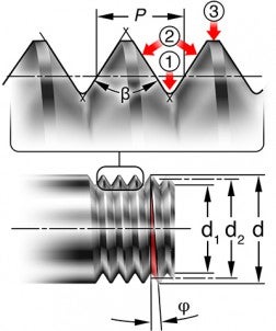
- Root/bottom
The bottom surface joining the two adjacent flanks of the thread - Flank/side
The side of a thread surface connecting the crest and the root - Crest/top
The top surface joining the two sides, or flanks.
P = Pitch, mm or threads per inch (t.p.i.)
The distance from a point on the screw thread to a corresponding point on the next thread measured parallel to the axis.
β = The thread profile angle
The angle between the flanks of the thread measured in an axial plane.
φ = Lead angle (helix angle) of the thread
The angle of the thread at a pitch diameter with a plane perpendicular to the axis.
Diameter parameters
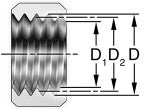
d = Major diameter, external
D = Major diameter, internal
d1 = Minor diameter, external
D1 = Minor diameter, internal
d2= Pitch diameter, external
D2= Pitch diameter, internal
The effective diameter of the screw thread; approximately half way between the major- and minor diameters.
Lead angle (helix angle)
The lead angle, φ, (helix angle) is dependent on and related to the diameter and the pitch of the thread. This measurement can be represented by a triangle being unwound from the component. The lead angle is calculated according to the formula below.

Formula for calculating the lead angle.
N = number of starts
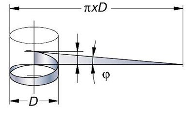
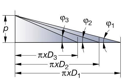
The same pitch on different diameters gives a different lead angle.
Thread milling formulas and definitions
Cutting speed (vc)
Metric (m/min)

Imperial (ft/min)

Formulas for internal thread milling
Calculated version
Peripheral feed (mm/min) (inch/min)

Radial depth of cut (mm)(inch)

Tool center feed (mm/min) (inch/min)

Feed per tooth (mm)(inch)


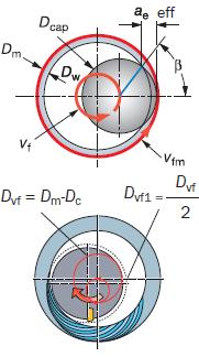
Thread milling with a roll into cut tool path, Dvf1
Formulas for external thread milling
Calculated version
Peripheral feed(mm/min)(inch/min)  | Tool center feed(mm/min)(inch/min)  |
Feed per tooth (mm) (inch)  |  |
 |
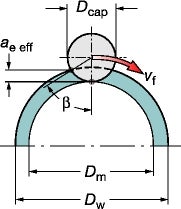
Tapping formulas and definitions
| Metric | Inch |
Spindle speed (n) (rpm)  |  |
Feed rate  |  |
Torque (Md) (Nm)  |
Power (P) (kW)  |
| Parameter | Meaning | Metric unit | Inch unit |
| Md | Torque | Nm | in.lb |
| p | Pitch | mm | inch |
| D / DC | Nominal diameter | mm | inch |
| kc | Specific cutting force | N/mm2 | lbs/in2 |
| n | Spindle speed | rpm (rev/min) | rpm (rev/min) |
| P | Power | kW | hp |
| vc | Cutting speed | m/min | Feet/min |
| vf | Feed rate | mm/min | in/min |
Formulas for hole size
A basic hole size calculation can be made with the following formulas.
Basic hole size calculation for Cutting tap
|
|
|
|
|

|
|
|
Basic hole size calculation for Forming tap

|
|
|
|

|
|
|
Basic hole size calculation with thread height for Cutting tap

|
|
|
|

|
|
|
Basic hole size calculation with thread height for forming tap

|
|
|
|

|
|
|
| Parameter | Meaning | Metric unit | Inch unit |
| D | Hole diameter | mm | inch |
| TD | Nominal thread diameter | mm | inch |
| TP | Thread pitch | mm | |
| TPI | Thread pitch inch | inch | |
| TH | Thread height | % | % |
How to calculate thread height in percentage, %
Thread height in %, is the ratio between actual height and maximum height of the internal thread. The example below applies to ISO & UTS standard – 60° threads.
Example, M8x1,25
Maximum thread height according to standard is 6/8 H.
H = 0.866 x P
(H = Basic triangle height)
(P = thread pitch)
Maximum thread height is:
6/8 * (0.866 x 1, 25) = 0.811 mm
Actual thread height at a core hole of Ø6.9 mm:
(8 - 6,9) / 2 = 0.55 mm
Thread height is then (0.55 / 0.81) x 100 = 68%
Actual thread height Rec core hole Ø | 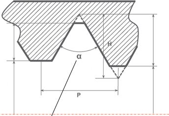 60° thread | Maximum thread height on internal thread (6/8 H) Min core hole Ø according to standard |
Thread designations according to international standards
International standards
To ensure that the two (internal and external) halves of a threaded joint fit together properly to produce a connection capable of bearing a specified load, threads must maintain certain standards. International standards for thread forms have therefore been established for all common thread types.
ISO metric thread designations
The complete thread designation is made up of values for the thread form and the tolerance. The tolerance is indicated by a number for the tolerance grade, and letters for the tolerance position.
Examples
M16 - 6h
M16: Thread designation and nominal dimension
6h: Tolerance class for pitch and crest position
M10 x 1.25 5g6g
M10: Pitch
1.25: Tolerance class for pitch diameter
5g6g: Tolerance class for crest diameter
A fit between threaded parts is indicated by the internal thread tolerance class followed by the external thread tolerance class, separated by an oblique stroke.
Tolerance positions
The tolerance position identifies the fundamental deviation and is indicated with an upper-case letter for internal threads and a lower case letter for external threads. A combination of tolerance grade and position give the tolerance class. The values of the tolerance classes are given in the standards for the different threading systems.
ISO inch threads (UNC, UNF, UNEF, UN)
The UN system has three tolerance classes, ranging from 1 (course) to 3 (fine). A typical UN thread is designated as follows:
¼”
20 20UNC - 2A
¼” – Major thread diameter
20 – Pitch value: threads per inch (t.p.i.)
UNC – Indicates a course pitch
2A – Indicates a medium tolerance
ISO – unified (UN):
Loose tolerance: 1A (external threads), 1B (internal threads)
Medium tolerance: 2A (external threads), 2B (internal threads)
Tight tolerance: 3A (external threads), 3B (internal threads)
Different types of UN thread
| UNC | thread diameter with course pitch |
| UNF | thread diameter with fine pitch |
| UNEF | thread diameter with extra-fine pitch |
| UN | thread diameter with constant pitch |
Whitworth threads (G, R, BSW, BSF, BSPF)
Whitworth screw threads are now obsolete, but Whitworth pipe threads are a recognized international standard. There are two tolerance classes for external-, and one tolerance class for internal Whitworth pipe threads.
Whitworth pipe threads: BSW, BSF and BSP.F
Tolerance position
Fine: A (external threads), internal threads one class only
Coarse: B (internal threads), internal threads one class only
Whitworth pipe thread designations
These threads are divided into 2 groups:
- Pressure-tight joints not made on the thread, ISO 228/1
- Pressure-tight joints made on the thread, ISO 7/1


