Slicing and trochoidal milling
Slicing and trochoidal milling methods were originally developed for roughing and semi-roughing of difficult materials such as hard steels, ISO H, and HRSA-materials, and ISO S, but can also be used with other materials, especially in vibration sensitive applications.
Trochoidal milling is primarily used for machining slots.
Slicing is usually used for semi-roughing of corners.
Both these methods have proven to be very secure and productive.
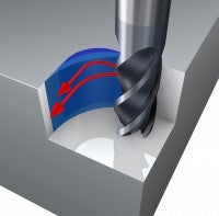
The slicing and trochoidal milling techniques are based on a small radial depth of cut, ae, which:
- Generates a low radial cutting force that places less demand on stability and enables a large depth of cut, ap
- Means that only one tooth is in cut at a time, which minimizes vibration tendency
- Reduces the heat in the cutting zone due to the short contact time, making it possible to use higher cutting speeds
- Generates a small chip thickness, hex, but a high feed, fz
Choice of tools
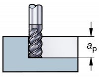
The slicing technique can also be used with long edge cutters that combine a small radial depth of cut, ae with a large axial depth of cut, ap.
How to apply slicing and trochoidal milling
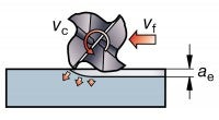
Slicing uses a higher cutting speed, vc, and an axial cut, ap, but with only small radial engagements, ae, and feed per tooth, fz. This is possibly due to:
- Factor Thin chip thicknessSmall arc of engagement
- Effect Lower cutting force/deflectionReduced temperature at cutting zone
- Benefit Deeper axial cutsHigher speeds
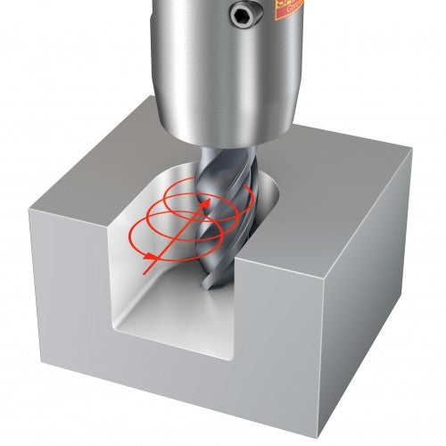
Trochoidal millingApplication area
An excellent method for slotting when vibration is a problem; it is also suitable for rough milling of confined cavities, pockets and grooves.Definition
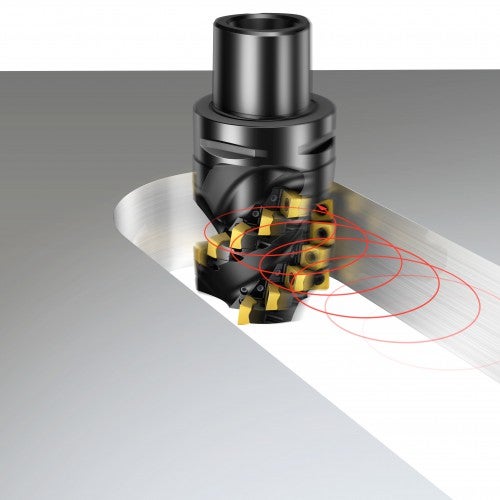
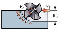
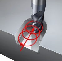
Trochoidal milling can be defined as circular milling that includes simultaneous forward movements. The cutter removes repeated "slices" of material in a sequence of continuous spiral tool paths in its radial direction.
It requires specialized programming and machine tool capabilities.
The tool is programmed with a roll entry into and exit from cut, with the radial pitch, w, kept low, which means that:
- The controlled arc of engagement generates low cutting forces, which enable high axial depths of cut
- The whole cutting edge length is utilized ensuring that heat and wear are uniform and spread out, leading to longer tool life than for traditional slot milling
- Due to the short arc of engagement, multi-edge tools are used, which enable high table feeds with secure tool life
- The maximum radial depth of cut, ae, should not exceed 20% of the cutter diameter
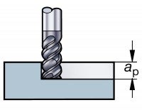
ap ≤ 2 x Dc
ae = small
vf = high
vc = up to 10 times that of conventional methods
For groove widths less than 2 x Dc
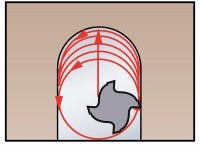
The tool is programmed on a continuous spiral path that feeds in the radial direction to form a groove or a profile. The feed is constant, with a continuously varying radial cut. The tool is out of cut 50% of the time.Considerations
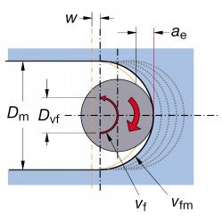
1) The radial cut is constantly changing and, at the greatest immersion, it is higher than the programmed step over, w.
2) It is important to keep the cutter diameter to a slot width ratio below 70%, and the radial pitch, w, below 10% of Dc.
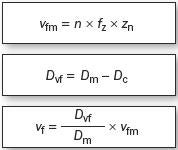
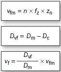
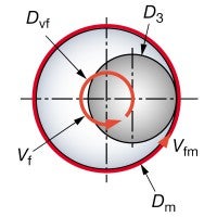
3) The feed is constant, however, the tool centre feed, vf, varies from the periphery feed, vfm. When the feed is programmed based on the tool centre, then the peripheral feed must be calculated.
Cutting parameters
- Max. cutter diaDc = 70% slot width
- Step overw = max. 10% Dc
- Radial cut max.ae = 20% Dc
- Axial cutap = up to 2 x Dc
- Start feed per toothfz = 0.1 mm
Calculate programmed feedvf
Trochoidal milling application tips
Trochoidal milling provides a more secure process compared to traditional slotting or plunging, with increased tool life and reduced tooling costs, as a 12 mm tool replaces an 8 mm tool.For grooves wider than 2 x Dc
A continuous spiral path, such as those programmed for the narrow groove where 50% of the time is spent with the tool out of the cut, can be optimized as the groove, becomes wider:
- Roll into cut – programmed radius (radm) = 50% of Dc.
- G1 with ae = 0.1 x Dc.
- Roll out of cut – programmed radius (radm) = 50% of Dc.
- Rapid movement to next start position.
- Repeat cycle.
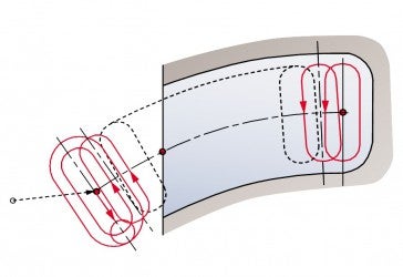
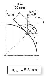
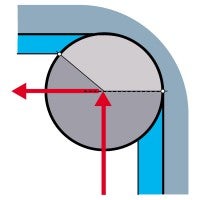
Slicing – corner milling
Application area
Slicing is a semi-roughing technique used in corner milling where the larger tool used in the previous operation cannot reach.Definition
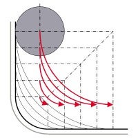
Unlike trochoidal milling, no roll into or from cut is required as the radial cut builds from zero to a maximum in the middle, and then drops back to zero again.
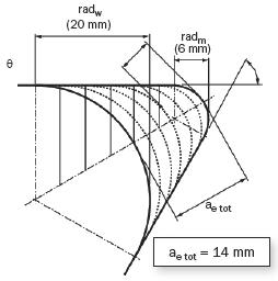
Multiple passes successively remove material ensuring consistent low radial immersion/engagement angle and low cutting forces.Considerations:
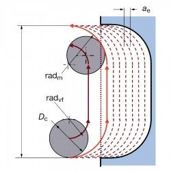
Feed rate reduction in corners:
- As with all radius contouring, when programming with a tool centre feed, vf, the feed rate needs to be reduced relative to the tool periphery feed, vfm, to maintain a constant feed per tooth
- Depth of cut can become too great to be able to run at same high feed as with straight line cutting, depending on cutter diameter to corner radius relationship
- However, the ratio between programmed cutter path diameter, Dvf, and hole diameter, Dm, is constantly increasing towards the finished corner radius, which means that the feed needs to continually decrease for each pass
- Process becomes unstable and vibration occurs
- A machine tool with good dynamic stability and tool centre feed reduction control is essential for successful milling of internal corners
Slicing
Conventional
Dvf and vf continually decrease for each pass
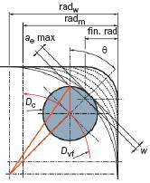
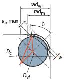
w = radial step over
radm = component end radius
radw = component start radius
For the same start and end radii, the number of passes required will vary depending upon the corner angle. For corners with angles less than 60˚, plunge milling using a plunge drill can be a good solution.Angle of corner