
Chamfer milling
Chamfers, V-cuts, undercuts, preparation for welding, and deburring operations along the workpiece edges are frequent chamfer milling operations. Depending upon the type of machine and set-up, these operations can be performed in a variety of ways. A small face mill, a long edge cutter, an end mill or chamfering cutters can be used.
Choice of tools
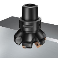
Chamfering cutters
The choice of chamfering tool depends on several factors, such as:
- If the operation is front chamfering or back chamfering
- Chamfering angle
- Max. chamfer depth
- Material to be machined
In front chamfer operations, one of the main consideration will also be the tool assembly available in the machine. For back chamfer operations, the hole size will also limit the size of the cutter and thus influence the tool choice. Typically, small chamfers in internal operations require a solid carbide tool for accessibility reasons, while larger features allow for indexable milling cutter to be used.
Complementary cutters for chamfering
In 4- and 5-axes machines, where the spindle or the workpiece can be tilted, a number of tools can be used for chamfering and deburring, such as:
- 90 degree end mills
- 45 degree face mills
- For large chamfers, long edge cutters can be used

How to apply
Cutting data
Normally the depth of cut, ap, and width of cut, ae, are small in relation to the cutter diameter. This means the higher cutting speed recommendations for small engagement should be used. The feed per tooth, fz, can also be considerably increased. The demands of the surface finish limit fz.
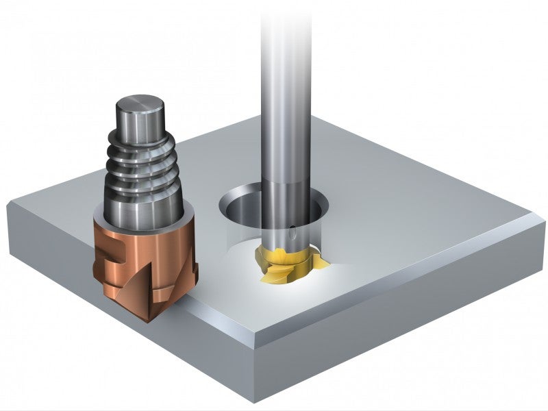
Chamfering a hole
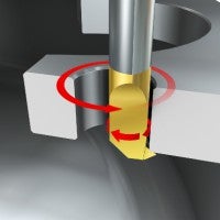
With some cutters that are able to do both chamfering and threading, it is possible to chamfer the hole after completing the threading operation, using the same tool and insert. This is performed using a circular milling path, see the programming sequence below.
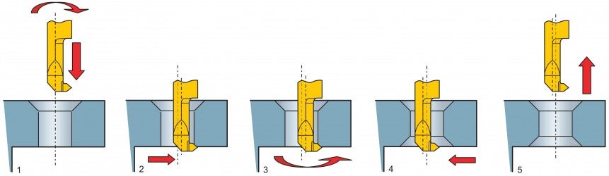
Zero point for tool length and radius
- Position the cutter centrally over the drilled hole, with the cutter rotating, and move axially to flange depth (Z = flange height – chamfer size)
- Feed the cutter to engage with the radius compensation (Y = hole radius)
- Interpolate 360
- Feed back to hole centre
- Retract cutter
Note: To adjust chamfer size, alter Z position (do not adjust diameter as this can cause rubbing on the hole).
