
Cutter path and chip formation in milling
Correct cutter path and chip formation in milling are important factors to ensure a secure cutting edge and better tool life in milling.
Each cutting edge of a milling cutter, in a radial direction, engages with the workpiece intermittently. There are three different phases in each engagement to consider:
1. Entrance into cut
2. Arc of engagement in cut
3. Exit from cut
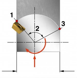
Entrance into cut
When using carbide inserts, the entrance into the cut is the least sensitive part of the three cutting phases. Carbide handles the compressive stresses at the impact of entering well.
Exit from cut
The exit from the workpiece is the most sensitive part of the three cutting phases.
Always try to avoid thick chip formation in milling on exit. A thick chip formation will often cause a drastic reduction in tool life when using carbide inserts. The chip lacks support at the final point of cut and tries to bend, which generates a tensile force on the carbide that can create a fracture on the edge.

Arc of engagement in cut
- The maximum possible arc of engagement is 180° (ae = 100% DC) when slotting
- For finish milling, the arc can be very small
- The grade requirements are quite different, depending on the percentage of radial immersion, ae/DC
- The larger the arc of engagement, the greater the heat transferred into the cutting edge
- With a large arc of engagement, CVD coated grades provide the best heat barrier
- With a small arc of engagement, the chip thickness is normally smaller, and the sharper edge on PVD coated grades generates less heat and reduced cutting forces
Large (max.) arc of engagement
- Long time in cut
- High radial forces
- More heat generated
- CVD coated grades

Small arc of engagement
- Short time in cut and less heat allows for higher vc
- Thinner chip allows for higher fz
- Sharp edges
- PVD coated grades
Entering the component
When the cutter is programmed to enter straight into the workpiece, thick chips will be produced at the exit until the cutter is fully engaged. This can dramatically reduce tool life, especially in harder steels, titanium and heat resistant alloys.Also, from a vibration point of view, it is essential to enter the workpiece smoothly.
There are two ways to increase tool life:1. Lower feed
Reduce feed to 50 percent until the cutter is fully engaged.2. Roll into cut
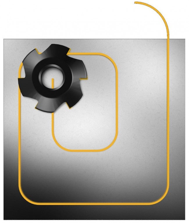
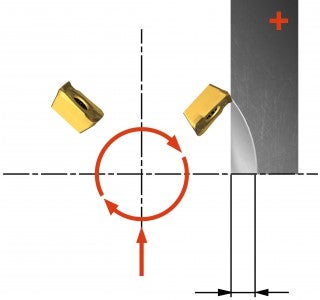
Program a roll into cut in a clockwise motion (anticlockwise will not solve the thick chip thickness problem). By rolling into cut, the chip thickness on exit is always zero, allowing for higher feed and longer tool life.
Cutter position
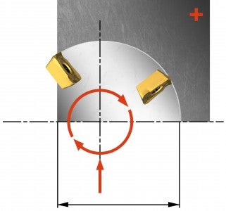
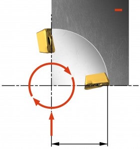
Position the cutter off-centre – to the left – to achieve a thicker chip at entry and a thin chip at exit (down milling method). A more constant and favourable direction of the cutting forces is obtained, minimizing vibration tendencies.
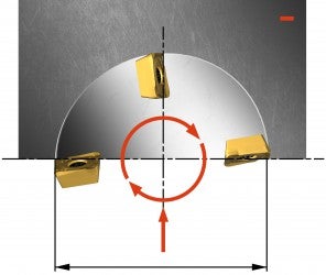
If the cutter is positioned symmetrically on the centre line, thick chips will be generated at exit and there is a higher risk for vibration tendencies.
The cutter diameter, DC, should be 20-50% larger than the width of cut, ae.
Available spindle power must also be considered as it influences the choice of pitch.
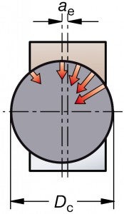
Cutter should be +20–50% larger than
ae and be positioned off-centre.
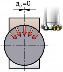
Cutter on centre line can
generate vibrations.
Keep cutter engaged
Sharp changes of direction in a cut will generate thick chips on exit. Follow these recommendations for a secure and optimized milling process:
- Keep the cutter constantly engaged
- Roll around all corners
- The width of cut, ae, should be 70% of DC to ensure maximum coverage of the corner
- In peripheral milling, roll around external corners
- Program around interruptions and holes when possible
