Export 3D model
When exporting a 3D model you have two different options, Export detailed 3D model or Export basic 3D model. The detailed 3D model represents how the tool assembly is looking when it’s not rotating, and the basic 3D model represents how the tool looks when it is rotating.
The CoroPlus® ToolLibrary supports 3D-STEP AP214 and AP242 files. Which format is exported by CoroPlus® ToolLibrary is defined in the default product handling configuration. You can change the default settings in the Administrator area. File names with special characters (ä, ö, ü, ~, @, *, +, !, ?, ß,...) are not allowed.
Nominal values
In models used for simulation matters, the dimensions must be in nominal values. The precision needs to be up to 3 decimals for mm drawings and up to 6 decimals for inch drawings. The software cuts off all decimals after the 3rd or respective 6th. For example, 10.0001 is considered as 10.
True-scale drawing
The scaling for drawings must be on a scale of 1:1. Scaling of individual drawing elements is not allowed.
Reference point
Adaptive items
The reference point is most of the time located at the plane gauge for adaptive items.
Cutting items
For cutting items with no fixed stop, the reference point is at the end.
For cutting items with a fixed stop, the reference point is on the stop surface.
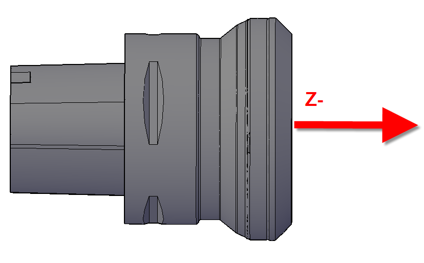
Orientation of items
The orientation in 3D is defined as Z-axis negative to the workpiece.
Definitions for CUT/NOCUT
If you want to use the models in simulation systems, you must differentiate among the cutting (CUT) and non-cutting parts (NOCUT) of an item. The differentiation is done with the colour attributes in the STEP-File. They are indicated via RGB values in an area from 0 to 1 (%) (1st parameter=red, 2nd parameter=green, 3rd parameter=blue). You can mostly find this information in the files as a percentage value, e.g., COLOUR_RGB ('', 1., 0.75, 0.)
| CUT part (color light grey) | 0.8 | 0.8 | 0.8 | 204 | 204 | 204 |
| NOCUT part (color grey) | 0.5 | 0.5 | 0.5 | 128 | 128 | 128 |
The CoroPlus ToolLibrary defines Colours as RGB values between 0 and 255.
For the CUT/NOCUT values inside the STEP file, the following RGB values must be used:
| 8 | Dark | 128 | ISO NoCutColor | 0.4982, | 0.5058, |
| grey | 128 | 0.4982, | 0.5058, | ||
| 128 | 0.4982, | 0.5058, | |||
| 252 | Lightest | 204 | ISO CutColor | 0.7962, | 0.8038, |
| grey | 204 | 0.7962, | 0.8038, | ||
| 204 | 0.7962, | 0.8038, |
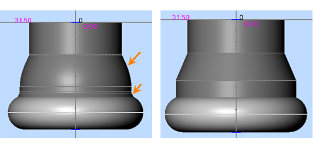
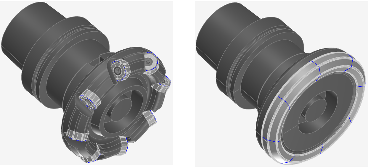
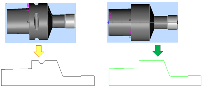
Level of detail for 3D solids
- Only simple models rotated: only cylinder, no chip space, no indexable inserts, no internal coolant, no “inner life”. Close the clamping chuck at the front. Otherwise, the drill is dangling in the air.
- Avoid radiuses, arcs and too many cylinders, which are not collision relevant. This makes simulation slow.
- Watch for items that are plugged into each other to ensure that the distance between them is not too great.
- Avoid gaps in the assembling area to get a volume model and not a surface model.
- For cutting tools: At least two bodies are necessary to differentiate between CUT/NOCUT.
- For standing tools: Planar cutting surfaces are necessary for indexable inserts.
- The resulting slice curves must consist of lines and arcs.
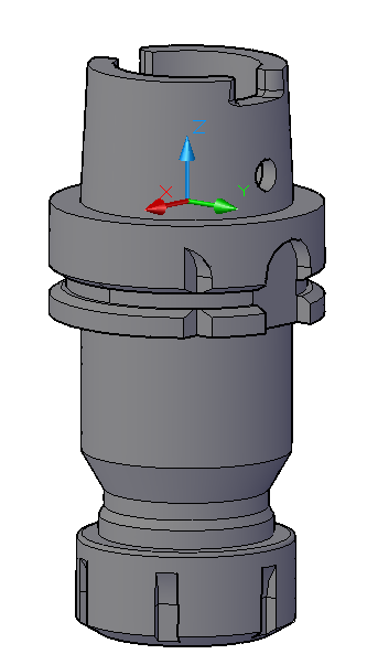
The Coromant Capto® shank (left image) is very detailed and might lead to a different shape if the contour is needed for the CAM Interface.
The cutter body consists of many arcs and few little lines. Therefore, for usage in simulation, a simplified geometry shown on the right is much better.