
Export 2D drawing
CoroPlus® ToolLibrary supports the 2D-DXF format in specific versions. It can process and display drawings starting with Release 11/12 (A1009). Loading older versions is not prohibited but can lead to unforeseeable results. Therefore, our recommendation is to use version 2000 as it is the current industry standard.
Nominal values
CoroPlus® Tool Library uses 2D drawings for simulations, therefore the dimensions must be in nominal values. The precision needs to be up to 3 decimals for mm drawings and up to 6 decimals for inch drawings. The software cuts off all decimals after the 3rd or respective 6th. For example, 10.0001 is considered as 10.
Accurate scale drawings
The scaling for drawings must be on a scale of 1:1. Scaling of individual drawing elements is not allowed.
Catalogue values
CoroPlus® Tool Library uses 2D drawings also for simulations, therefore the dimensions must be according to catalogue values. The precision needs to be up to 3 decimals for mm drawings and up to 6 decimals for inch drawing. The software cuts off all decimals after the 3rd or respective 6th. For example, 10.0001 is considered as 10. The unit of measurement defined in the drawing must be according to the provided catalogue values.
Reference point
Adaptive items
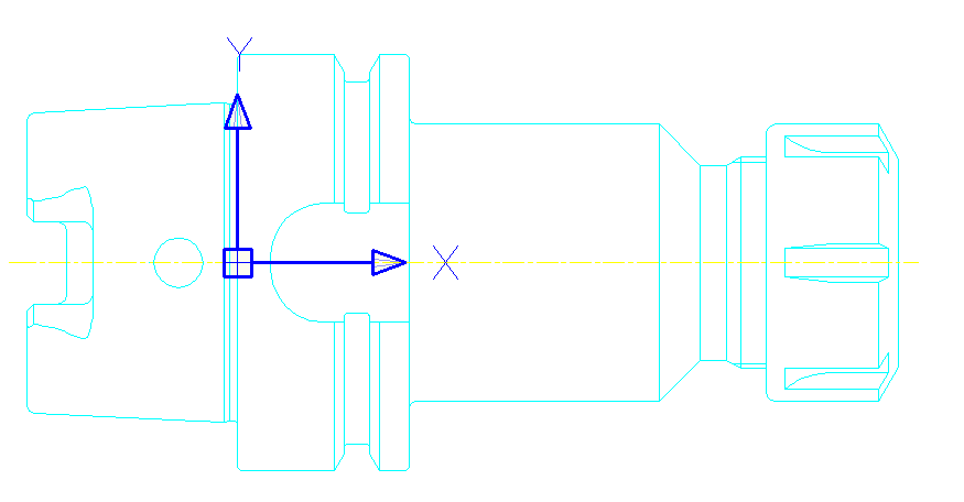
The reference point is most of the time located at the plane gauge for an adaptive item.
Cutting items
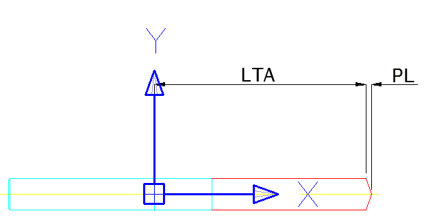
For cutting items that have no fixed stop, the reference point is at LTA.
For cutting items with a fixed stop, the reference point is on the stop surface.
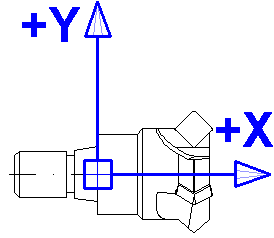
Orientation
The orientation in 2D is defined as X-axis towards the workpiece.
Layer structure
2D drawings used in the CoroPlus® ToolLibrary must adhere to the layer structure defined by ISO13399 Part 70. While loading the drawings, the software applies the defined colours, fonts and line types. For the tool assemblies, a set of layers and their SK pendants have an important influence. In the following table, you can find a list of layers that are usually used for item drawings:
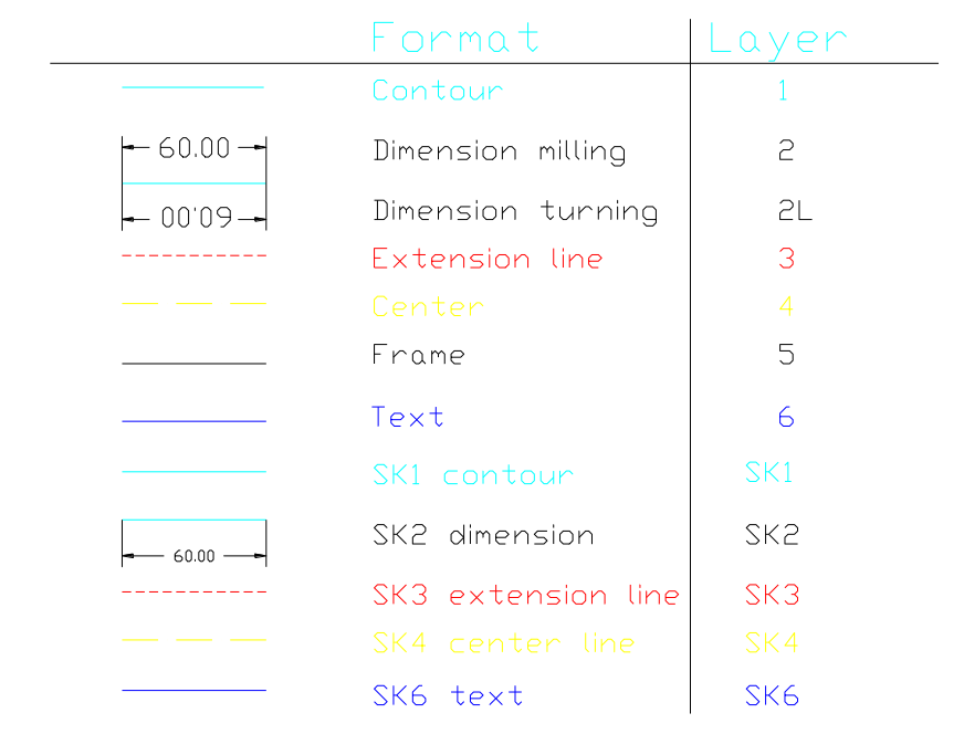
| Contour | 1 | Cyan | 0,255,255 | Visible external outline for the tool assembly and item drawing |
| Dimension | 2 | White | 255,255,255 | Dimension of the tool assembly and item drawings |
| Help line | 3 | Red | 255,0,0 | Help geometries of tool assembly and item drawings |
| Center line | 4 | Yellow | 255,255,0 | Center line only for the tool assembly |
| Frame | 5 | White | 255,255,255 | Drawing and text elements of the item or tool assembly sheet |
| Text | 6 | Blue | 0,0,255 | Text elements of the item or tool assembly drawings and the hatch of the indexable inserts |
| Hatch | 7 | Blue | 0,0,255 | Hatch of the tool assembly and item drawing |
| SK1 Contour | SK1 | Cyan | 0,255,255 | Outline elements only for items |
| SK2 Dimension | SK2 | White | 255,255,255 | Dimension only visible in single items |
| SK3 Help line | SK3 | Red | 255,0,0 | Help geometries only for items |
| SK4 Center line | SK4 | Yellow | 255,255,0 | Center line only visible in single items |
| SK6 Text | SK6 | Blue | 0,0,255 | Label of the item |
| SK7 Hatch | SK7 | Blue | 0,0,255 | Hatch of the item |
The line types, descriptions and colours of the single layers are shown in the following image:
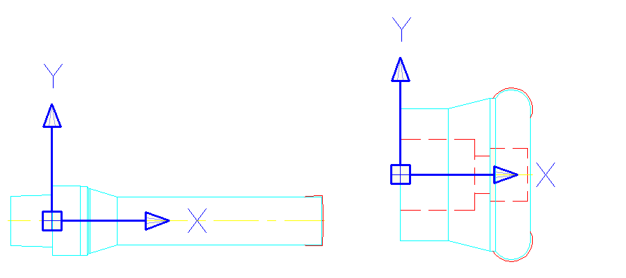
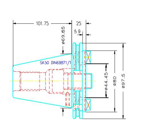
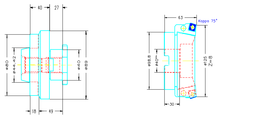
Item view
The example shows three items which are part of a milling tool assembly. On the item level most of the layers are presented.
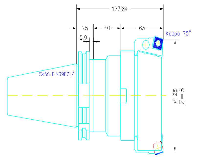
Tool assembly view
Some of the layers are cut off, to make the tool assembly drawing look clean and understandable.
Observe content limitations
If 2D drawings are exported to external applications for simulations, they must adhere to specific rules regarding their content. Please observe the following limitations:
- No splines
- No polylines 3D
- No double elements: Avoid objects being within an area of 0.2 units around an object and on the same layer as the overlapping element.
- No gaps in the outline
- The object coordinate system (OCS) must conform to the current world coordinate system (WCS).
- No drawing elements are allowed to use values in the Z-axis. All elements must be placed on the XY plane.
- No unreferenced blocks
