Sandvik Coromant logo

Troubleshooting for thread turning

Careful observation of the insert/cutting edge after machining can help to optimize results regarding tool life, thread quality, and cutting speed. Use this list of causes and solutions to different forms of insert wear as a reference for successful threading.


Plastic deformation

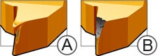
Starts as plastic deformation (A),
which leads to edge chipping (B).

  1. Excessive temperature in cutting zone
  2. Inadequate supply of coolant
  3. Wrong grade
  1. a) Reduce the cutting speed, increase the number of infeeds
    b) Reduce the largest infeed depth, check the diameter before threading
  2. Improve coolant supply
  3. Choose a grade with better resistance to plastic deformation

Built-up edge (BUE)

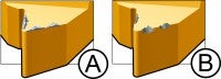
BUE (A) and edge chipping (B) often
occur in combination. Accumulated
BUE is then ripped away, together
with small amounts of insert material,
which leads to chipping.

  1. Often occurs in stainless steel and low-carbon steel
  2. Unsuitable grade, or cutting edge temperature too low
  1. Increase cutting speed
  2. Choose an insert with good toughness, preferably PVD-coated


Insert breakage

  1. Wrong turned diameter prior to threading
  2. Infeed series too tough
  3. Wrong grade
  4. Poor chip control
  5. Incorrect center height
  1. Turn to correct diameter before threading, 0.03–0.07 mm
    (0.001–0.003 inch) radially larger than max. diameter for thread
  2. Increase number of infeeds. Reduce size of the largest infeed
  3. Choose a tougher grade
  4. Change to C-geometry, and use modified flank infeed
  5. Correct center height

Rapid flank wear

  1. Highly abrasive material
  2. Cutting speed too high
  3. Infeed depths too shallow
  4. Insert is above center line
  1. Wrong grade. Choose a more wear-resistant grade
  2. Reduce cutting speed
  3. Reduce number of infeeds
  4. Correct center height

Abnormal flank wear

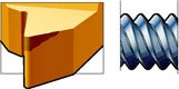
Poor surface on one thread flank

  1. Incorrect method for flank infeed
  2. Insert inclination angle does not agree with
    the thread lead angle
  1. Change method of flank infeed for F- and A-geometry:
    3–5° from flank, for C-geometry: 1° from flank
  2. Change shim to obtain correct angle of inclination

Vibration

  1. Incorrect workpiece clamping
  2. Incorrect tool setup
  3. Incorrect cutting data
  4. Incorrect center height
  1. a) Use soft jaws
    b) Optimize component centering hole when using tail stock,
    and check pressure of tail stock/face driver
  2. a) Minimize tool overhang
    b) Make sure the clamping sleeve for bars is not worn
    c) Use anti-vibration bars dedicated for thread turning
  3. Increase cutting speed; if this does not help, lower the speed dramatically,
    and try F-geometry
  4. Correct center height

Join us. Stay updated.

Sign up for our newsletter today

account_circle

欢迎,