Cutting tool parameters according to ISO 13399
All cutting tools are defined by a number of parameters according to the standard ISO 13399. You will find both the cutting tool parameter and its definition in this list.

What is ISO 13399?
ISO 13399 is an international cutting tool information standard. Each cutting tool is defined by a number of these standardized ISO 13399 parameters. The standard provides cutting tool information in a neutral format that is independent of any particular system or company nomenclature. With tools that are clearly defined according to a standard that all software can process, the quality of communication gets better, and the electronic data exchange between systems runs smoothly. The data gathering process will be more efficient and of higher quality. Ultimately, the standard saves time and provides an extra guarantee of quality. A common language is valuable from a system to system point of view, but will also make life easier for users. Once you have an ISO 13399 compliant system, there will be no need to manually interpret data from paper catalogs and then key it into your system.
| Parameter | Definition |
| ADINTMS | Adaptive interface machine direction |
| ADINTWS | Adaptive interface workpiece direction |
| AERMX | Working engagement ratio maximum |
| ALP | Axial clearance angle |
| AN | Clearance angle major |
| ANN | Clearance angle minor |
| APMX | Depth of cut maximum |
| AXGSUP | Axial groove support direction |
| AZ | Maximum plunge depth |
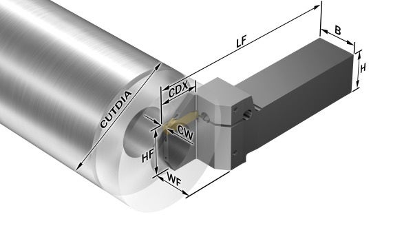
| B | Shank width |
| BAMS | Machine side body angle |
| BAWS | Workpiece side body angle |
| BBD | Balanced by design |
| BBR | Balanced by rotational test |
| BD | Body diameter |
| BHTA | Body half taper angle |
| BLMC | Balancing method code |
| BMC | Body material code |
| BN | Face land width |
| BS | Wiper edge length |
| BSG | Identifier for the standard defining the tool design |
| BSR | Wiper edge radius |
| CBMD | Chip breaker manufacturer's designation |
| CCC | Center cutting capability |
| CCONWS | Workpiece side connection count |
| CDX | Cutting depth maximum |
| CEDC | Cutting edge count |
| CGX | X-component for center of gravity location |
| CGY | Y-component for center of gravity location |
| CGZ | Z-component for center of gravity location |
| CHW | Corner chamfer width |
| CICT | Cutting item count |
| CND | Coolant entry diameter |
| CNSC | Coolant entry style code |
| CNT | Coolant entry thread size |
| COATING | Coating |
| CONARWS | Connection arrangement workpiece side |
| CP | Coolant pressure |
| CPDF | Cutting pitch differential |
| CRKS | Connection retention knob thread size |
| CTPT | Operation type |
| CUTDIA | Work piece parting diameter maximum |
| CUTINT_MASTER | Part two of two identifiers of cutting item interface |
| CUTINT_SIZESHAPE | Insert size and shape |
| CW | Cutting width |
| CWTOLL | Cutting width lower tolerance |
| CWTOLU | Cutting width upper tolerance |
| CXSC | Coolant exit style code |
| CXST | Coolant exit supply type |
| CZC | Connection size code |
| CZC MS | Connection size code machine side |
| CZC WS | Connection size code workpiece side |
| D1 | Fixing hole diameter |
| DAH | Diameter access hole |
| DAXIN | Axial groove inside diameter minimum |
| DAXN | Minimum axial groove outside diameter |
| DAXX | Maximum axial groove outside diameter |
| DBC | Diameter bolt circle |
| DC | Cutting diameter |
| DCB | Connection bore diameter |
| DCBN | Connection bore diameter minimum |
| DCBX | Connection bore diameter maximum |
| DCF | Cutting diameter face contact |
| DCN | Minimum cutting diameter |
| DCON | Connection diameter |
| DCONMS | Connection diameter machine side |
| DCONWS | Connection diameter workpiece side |
| DCP | Data chip pocket |
| DCPS | Data chip pocket size |
| DCSFMS | Contact surface diameter machine side |
| DCSFWS | Contact surface diameter workpiece side |
| DCTOLL | Lower cutting diameter tolerance |
| DCTOLU | Upper cutting diameter tolerance |
| DCX | Maximum cutting diameter |
| DFC | Functional diameter |
| DHUB | Hub diameter |
| DIX | Tool changer interference diameter maximum |
| DMIN | Minimum bore diameter |
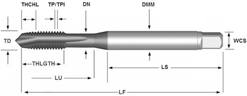
| DMM | Shank diameter |
| DN | Neck diameter |
| DPC | Damping property |
| DSGN | Design |
| FHA | Flute helix angle |
| FLGT | Flange thickness |
| FTDZ | For thread diameter size |
| GAMF | Radial rake angle |
| GAMO | Orthogonal rake angle |
| GAMP | Axial rake angle |
| GAN | Insert rake angle |
| GB | Face land angle |
| GRADE | The brand name for grade |
| H | Shank height |
| HAND | Hand |
| HBL | Head bottom offset length |
| HDD | Head diameter |
| HEAD_TYPE | Type of head |
| HF | Functional height |
| HRY | Lowest point from reference plain |
| HTB | Body height |
| HTH | Height |
| HTY | Hole type |
| IC | Inscribed circle diameter |
| IEP | Interupted edge property |
| IFS | Insert mounting style code |
| INSL | Insert length |
| IZC | Insert size code |
| KAP | Kappa (z-axis rot) |
| KAPR | Tool cutting edge angle |
| KCH | Corner chamfer |
| KGRP_INT | Key grip interface |
| KGRPS | Size of driven part |
| KGRPTP | Geometrical characteristic driven part |
| KRINS | Major cutting edge angle |
| L | Cutting edge length |
| LAMS | Inclination angle |
| LB | Body length |
| LCF | Chip flute length |
| LE | Cutting edge effective length |
| LF | Functional length |
| LGR | Regrind length |
| LH | Head length |
| LIG | Insert gauge length |
| LOCAP | Location aid property |
| LPR | Protruding length |
| LS | Shank length |
| LSC | Clamping length |
| LSCN | Clamping length minimum |
| LSCX | Clamping length maximum |
| LSD | Dead shank length |
| LU | Usable length |
| MHD | Mounting hole distance |
| MIID | Master insert identification |
| MMCC | Code for preset torque |
| MMCX | Maximum cutting torque |
| MRAT | Main rotation angle of tool |
| MTP | Clamping type code |
| NOF | Flute count |
| NORGMX | Maximum regrinds |
| OAH | Overall height |
| OAL | Overall length |
| OAW | Overall width |
| OHN | Minimum overhang |
| OHX | Maximum overhang |
| PHD | Premachined hole diameter |
| PHDX | Maximum premachined hole diameter |
| PHT | Premachined hole type |
| PL | Point length |
| PRFRAD | Profile radius |
| PRSPC | Profile specification |
| PSIR | Tool lead angle |
| PSIRL | Major left hand cutting edge angle |
| PSIRR | Major right hand cutting edge angle |
| RADH | Radial body height |
| RADW | Radial body width |
| RE | Corner radius |
| REEQ | Corner radius equivalent |
| REL | Corner radius left |
| RER | Corner radius right |
| RETOLL | Corner radius lower tolerance |
| RETOLU | Corner radius upper tolerance |
| RIDOP | Reversed rotation direction output side |
| RMPX | Maximum ramping angle |
| RPMX | Rotational speed maximum |
| S | Insert thickness |
| SC | Insert shape code |
| SCREW_TYPE | Screw type |
| SDL | Step diameter length |
| SEAL | Sealing property |
| SEP | Sensor embedded property |
| SIG | Point angle |
| SPA | Sphere profile angle |
| SSC | Insert seat size code |
| STA | Step included angle |
| SUBSTRATE | Substrate |
| TA | Taper angle |
| TCDC | Tolerance class cutting diameter |
| TCDCON | Connection diameter tolerance |
| TCDMM | Shank diameter tolerance |
| TCHA | Achievable hole tolerance |
| TCL | Tap chamfer length |
| TCT | Tolerance class tool |
| TCTR | Thread tolerance class |
| TD | Thread diameter |
| TDZ | Thread diameter size |
| TFLA | Tap floating length ahead |
| TFLB | Tap floating length behind |
| TG | Taper gradient |
| THBTP | Thread back taper property |
| THCA | Thread helix correction angle |
| THCHT | Threading chamfer type |
| THDH | Thread hand |
| THFT | Form type |
| THL | Threading length |
| THLGTH | Thread length |
| THUB | Hub thickness |
| TP | Thread pitch |
| TPI | Threads per inch |
| TPIN | Threads per inch minimum |
| TPIX | Threads per inch maximum |
| TPN | Thread pitch minimum |
| TPX | Maximum thread pitch |
| TQ | Torque |
| TSYC | Tool style code |
| ULDR | Usable length diameter ratio |
| W1 | Insert width |
| WB | Body width |
| WEP | Wiper edge property |
| WF | Functional width |
| WSC | Clamping width |
| WT | Weight of item |
| XYPFEEDIR | XY-plane feed direction |
| ZEFF | Number of cutting edges that are effective on the face of a tool |
| ZEFP | Peripheral effective cutting edge count |
| ZWX | Maximum number of Wiper inserts |