
Drilling wear and troubleshooting
Troubleshooting
- Indexable insert drill
- Exchangeable-tip drill
- Solid carbide drill
Indexable insert drill
Oversized holes
Rotating drill
- Increase coolant flow, clean filter and clear coolant holes in drill
- Try a tougher geometry on the peripheral side (keep center insert)
Non-rotating drill
- Check alignment on lathe
- Rotate drill 180 degrees
- Try a tougher geometry on the peripheral side (keep center insert)
Undersized holes
Rotating drill
- Increase coolant flow, clean filter and clear coolant holes in drill
- Try a tougher geometry on the center side and a light cutting geometry on the peripheral side
Non-rotating drill
- Stationary: Check alignment on lathe
- Stationary: Rotate drill 180 degrees
- Try a tougher geometry at the center and a light cutting geometry at the periphery
Pin in hole
Rotating drill
- Increase coolant flow, clean filter and clear coolant holes in drill
- Try a different geometry on the peripheral side and adjust feed rate within recommended cutting data
- Shorten drill overhang
Non-rotating drill
- Check alignment on lathe
- Increase coolant flow, clean filter and clear coolant holes in drill
- Shorten drill overhang
- Try a different geometry on the peripheral side and adjust feed rate within recommended cutting data
Vibrations
- Shorten drill overhang, improve the workpiece stability
- Reduce cutting speed
- Try a different geometry on the peripheral side and adjust feed rate within recommended cutting data
Insufficient machine torque
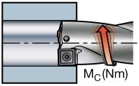
- Reduce feed
- Choose a light cutting geometry to lower the cutting force
Insufficient machine power
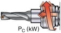
- Reduce speed
- Reduce feed
- Choose a light cutting geometry to lower the cutting force
Hole not symmetrical
Hole widens at bottom (due to chip jam on center insert)
- Increase coolant flow, clean filter and clear coolant holes in drill
- Try a different geometry on the peripheral side and adjust feed rate within recommended cutting data
- Shorten drill overhang
Poor tool life
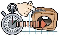
- Check cutting data recommendation
- Increase coolant flow, clean filter and clear coolant holes in drill
- Shorten drill overhang, improve the workpiece stability and check tool holding
- Check tip/insert seat and screw for damage
- See typical wear for specific remedies
- Choose a more wear-resistant grade, if possible
Broken insert screws
- Use torque wrench to fasten the screw together with Molykote
Bad surface finish
- Important to have good chip control
- Reduce feed (if it is important to keep vf, increase speed as well)
- Increase coolant flow, clean filter and clear coolant holes in drill
- Shorten drill overhang, improve workpiece stability
Chip jamming in the drill flutes
Caused by long chips
- Check geometry and cutting data recommendations
- Increase coolant flow, clean filter and clear coolant holes in drill
- Reduce feed within recommended cutting data
- Increase cutting speed within recommended cutting data
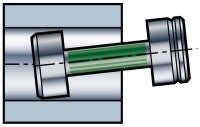
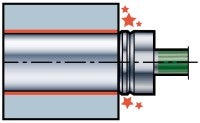
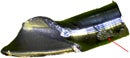
Deflection
- Hole tolerance out of range
- Bad surface finish – retraction mark
- Wear on tool body
- Insert breakage
| Cause | Solution |
| Cutting forces too high | 1. Choose geometry with smaller corner radius 2. Reduce feed 3. Reduce feed at entrance |
| Insufficient stability | 1. Increase stability 2. Choose a shorter tool body (4 × D -> 3 × D) |
Chip forming problems
Long-chipping materials, e.g. stainless or low-carbon steel
| Result | Possible cause | Solution |
| Bad/long chips – chip jamming | Wrong geometry | Choose geometry -LM |
| Bad surface finish | Cutting speed too low | Increase cutting speed |
| Insert or tool breakdown | Feed too high | Decrease feed |
Short-chipping materials, e.g. normal steel
| Result | Possible cause | Solution |
| Bad/long chips – chip jamming | Non-rotating tool (lathe) | Choose geometry for low feed (GR -> GM) |
| Bad surface finish | Wrong geometry | Increase feed |
| Insert or tool breakdown | 1. Cutting speed too low 2. Feed too low | Increase cutting speed |
Exchangeable-tip drill
Out-of-hole tolerance
- Check tip wear
- Check run-out
- Decrease feed
- Check workpiece stability, tool holding and workpiece surface
- Pilot/spot drill for longer drills
- If non-rotating application, check alignment
Vibration
- Shorten drill overhang, improve workpiece stability, check tool holding
- Reduce cutting speed
- Adjust feed/rev
Insufficient machine power or torque
- Reduce speed
- Reduce feed
- Choose a light cutting geometry to lower the cutting force
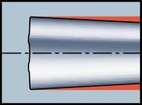
Hole not cylindrical
Hole widens at entrance
- Check run-out
- Adjust feed
- Shorten drill overhang and check tool holding
- Make a pilot hole with a short drill for longer drills
Poor tool life
Check cutting data recommendation
- Increase coolant flow, clean filter and clear coolant holes in drill
- Shorten drill overhang, improve workpiece stability and check tool holding
- Check tip/insert seat and screw for damage
- See typical wear for specific remedies
- Choose a more wear-resistant grade, if possible
Bad surface finish
- Important to have good chip control
- Reduce feed (if it is important to keep vf, also increase speed)
- Increase coolant flow, clean filter and clear coolant holes in drill
- Shorten drill overhang, improve the workpiece stability
Chip jamming in the drill flutes
- Adjust cutting data for improved chip control
- Increase coolant flow, clean filter, clear coolant holes in drill, check coolant concentration
- Problems with chip jamming can cause extreme drill body wear
- Remove any workpiece material stuck on the drill body to avoid chip jamming
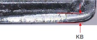
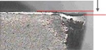
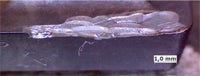
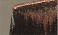
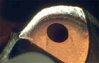
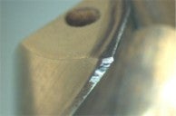
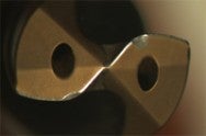
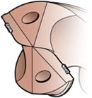
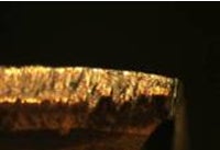
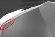
Entrance chip
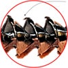
"Needles" on the periphery
- Risk of excessive wear if needles can be seen on the start-chip periphery
- Probable cause – imbalance due to: Run-outInclined entranceFeed too highUnstable/weak conditionsCorner breakage/wear
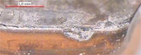
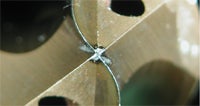
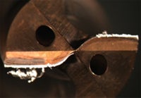
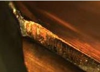
Chip control – optimization
- A scratch mark on the chips, as seen above, is a sign of chip jamming, which influences hole quality negatively. To improve hole quality, the recommendation is to reduce feed and, if possible, increase speed
Solid carbide drill
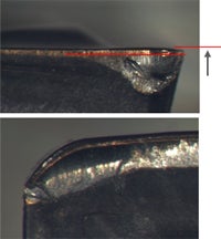
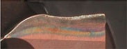
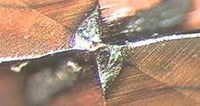
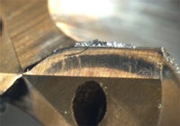
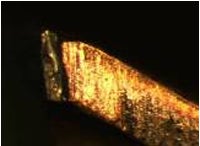
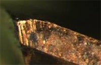
Entrance chip – solid carbide/exchangeable-tip drills
"Needles" on the periphery
- Risk of excessive wear if needles can be seen on the start-chip periphery
- Probable cause – imbalance due to: Run-outInclined entranceFeed too highUnstable/weak conditionsCorner breakage/wear
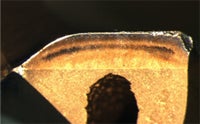
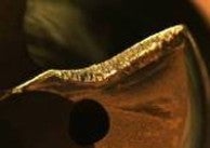
Chip control – optimization
- A scratch mark on the chips, as seen above, is a sign of chip jamming, which influences hole quality negatively. To improve hole quality, the recommendation is to reduce feed and, if possible, increase speed
Drilling wear types
- Indexable insert drills
- Exchangeable-tip drill
- Solid carbide drill
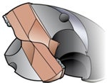
Indexable insert drills
Flank wear
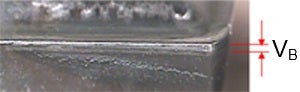
Flank wear is the preferable wear type when balanced. Flank wear can result in
- Poor surface finish
- Hole tolerance out of range
- Power increase
| Cause | Action |
| 1. Cutting speed too high (vc) | 1. Decrease cutting speed (vc) |
| 2. Insufficient wear resistance in grade | 2. Select a more wear-resistant grade |
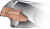
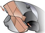
Crater wear
Central insert
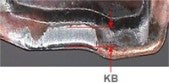
Peripheral insert
Crater wear can result in
- Weak cutting edge that can cause edge breakage and generate bad chips
- Poor surface finish
- Power increase
| Cause | Action |
| Central insert: abrasive chips (workpiece material) | Central insert: reduce feed |
| Peripheral insert: diffusion wear caused by high temperature (worse for PVD) | Peripheral insert: 1. Decrease cutting speed 2. Select a more wear-resistant grade (often MT-CVD) |
| Select a more positive geometry for better chip formation |
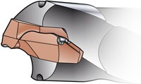
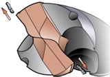
Plastic deformation
Depression
Impression
Edge depression or impression can cause poor chip control, poor surface finish and the hole to be out of tolerance.
| Cause | Action |
| Cutting temperature too high, combined with high pressure (feed and/or workpiece hardness) | Decrease feed (fn) Select grade with better resistance against PD (hot hardness) Decrease cutting speed (vc) |
| A final result of excessive flank and/or crater wear | Select grade with better resistance against PD (hot hardness) Decrease cutting speed (vc) |
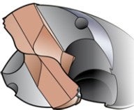
Chipping in cutting zone
Chipping in cutting zone can result in
- Exaggerated flank wear
- Poor surface finish
| Cause | Action |
| Unstable conditions | Improve stability (tool overhang, fixating) |
| Irregular surface | Reduce feed at entrance. Choose tougher geometry |
| Insufficient toughness of grade | Select a tougher grade |
| Insert geometry too weak | Select a stronger geometry |
| Insufficient cutting fluid | Increase cutting fluid |
| Sand inclusions (cast iron) | Choose a stronger geometry, reduce feed |
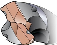
Breakage
Breakage can result in
- Tool breakdown
- Destroyed workpiece
| Cause | Action |
| Insufficient stability | Improve stability (shorten tool overhang, better workpiece fixturing, etc.) |
| Intermittent cutting | Reduce feed, choose tougher geometry (-GR or -GT) |
| Insufficient cutting fluid | Increase cutting fluid |
| Feed too high or cutting speed too high/low | Adjust cutting data |
| Grade too brittle (P-insert) | Choose a tougher grade |
| Insert worn out | Determine safe tool life on peripheral insert |
Built-up edge (BUE)
Built-up edge can result in
- Poor surface finish and edge frittering when BUE is ripped away by chips
- Chipping of cutting edge
| Cause | Action |
| Unfavorable temperature (cutting speed) | Increase/decrease cutting speed (high/low temperature) Select a coated grade |
| Cutting geometry too negative | Select a more positive geometry |
| Sticky material | Increase oil mixture and volume/pressure in cutting fluid |
| Oil mixture in cutting fluid too low | Increase oil mixture and volume/pressure in cutting fluid |
Exchangeable-tip drill
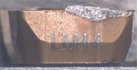
Typical wear in different materials for -PM geometry
Unalloyed steel / CMC01.1
- Margin/periphery wear starts as notch and develops along margin width and into flute
- Continuously growing wear on main edge
Low-alloy steel / CMC02.2
- Continuously growing wear on main edge/margin close to corner
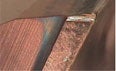
Flank wear
Flank wear on main edge
Flank wear on circular land
Normal and preferable wear type when balanced
| Cause | Action |
| Cutting speed too high | Decrease cutting speed |
| Percentage of oil in cutting fluid flow too low | Increase percentage of oil in cutting fluid (check with oil distributor to be sure not to exceed recommended percentages of oil) |
| Insufficient cutting fluid flow | Increase cutting fluid flow |
| Total indicator run-out too large (if wear on margin) | Check radial run-out (if wear on margin) |
Plastic deformation
| Cause | Action |
| Cutting speed and/or feed too high | Decrease cutting speed and/or feed |
| Insufficient cutting fluid flow | Increase cutting fluid flow |
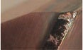
Chipping
Chipping on periphery
Chipping on main edge
Chipping is a very common wear type when drilling into a pre-drilled hole. If the point angle is smaller on the pre-drilled hole, stability will be poor and the corners can be damaged. This can also happen if tolerances on point angles do not match. This can be avoided with custom-made drills or with flat bottom holes made by milling.
| Cause | Action |
| Unstable conditions | Check set-up |
| Total indicator run-out too large | Check radial run-out |
| Feed too high | Decrease feed |
| Insufficient cutting fluid flow (thermal cracking) | Check cutting fluid supply |
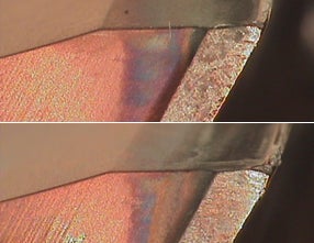
Built-up edge
| Cause | Action |
| Unsuitable cutting speed | 1. Increase cutting speed when BUE in center 2. Decrease cutting speed when BUE in periphery |
| Percentage of oil in the cutting fluid too low | Increase percentage of oil in cutting fluid (check with oil distributor to be sure not to exceed recommended percentages of oil) |
If you cannot fully avoid the BUE zone, calculate a speed that locates the BUE in the strongest part of the drill (= 50% of diameter).
The use of external cutting fluid can influence chip evacuation negatively.
Increase cutting speed to move BUE
towards BUE center of the drill
Decrease cutting speed to move
to periphery or eliminate BUE
Solid carbide drill
Flank wear
Flank wear on main edge
Flank wear on circular land
Preferable wear type when balanced
| Cause | Action |
| Total indicator run-out too large | Check radial run-out |
| Cutting speed too high | Decrease cutting speed |
| Feed too low | Increase feed |
| Grade too soft | Use a harder grade |
| Insufficient cutting fluid | Increase cutting fluid pressure |
Flank wear on chisel edge
| Cause | Action |
| Total indicator run-out too large | Check radial run-out |
| Cutting speed too low | Increase cutting speed |
| Feed too high | Decrease feed |
Flank wear on chisel edge will also influence hole quality due to bad centering.
Chipping
Chipping on periphery
Chipping on main edge
Chipping is a very common wear type when drilling into a pre-drilled hole. If the point angle is smaller on the pre-drilled hole, stability will be poor and the corners can be damaged. This can also happen if tolerances on point angles do not match. This can be avoided with custom-made drills or with flat bottom holes made by milling.
| Cause | Action |
| Unstable conditions | Check set-up |
| Total indicator run-out too large | Check radial run-out |
| Insufficient cutting fluid (thermal cracking) | Check cutting fluid supply |
| Maximum allowed wear exceeded | Adjust cutting data |
Drill breakage
| Cause | Action |
| Total indicator run-out too large | Check radial run-out |
| Unstable conditions | Check set-up |
| Insufficient spindle power | Check cutting data |
| Chip jamming | Check cutting fluid supply |
| Feed too high | Decrease feed |
| Excessive wear | Check wear more frequently |
Built-up edge
| Cause | Action |
| Cutting speed and edge temperature too low | 1. Increase cutting speed when BUE in center 2. Decrease cutting speed when BUE in periphery |
| Negative land too large | Sharper cutting edge |
| No coating | Coating on the edge |
If you cannot fully avoid the BUE zone, calculate a speed that locates the BUE in the strongest part of the drill (= 50% of diameter).
The use of external cutting fluid can influence chip evacuation negatively.
Increase cutting speed to move
BUE towards center of the drill
Decrease cutting speed to move
BUE to periphery or eliminate BUE
Typical wear
Regardless of material
- Always flank wear
- Chipping is seldom seen Process security
Unalloyed steel / CMC01.1
- Margin/periphery wear Wear starts as notchGrows towards corner
Low-alloy steel / CMC02.2
- Corner wear
High-alloy steel / CMC03.11
- Significant flank wear
- Small damages on corner
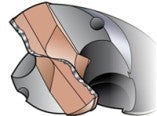
Corner design
Caution!
- Do not misjudge the reinforcement as wear
Troubleshooting
Oversized thread Cause Solution Wrong tolerance Wrong tap for application Incorrect... chevron_right
Troubleshooting
Main problems Spindle or tool runout is too high Wrong cutting data Built-up edge When... chevron_right
Tips film - Analyze tool wear in solid carbide drilling
The goal in solid carbide drilling is to obtain a balanced wear across the drill’s... open_in_new
Cutting tool materials
Introduction The selection of the cutting tool material and grade is an important... chevron_right
