
Shoulder milling
Shoulder milling operations include:
- Shoulder/ face milling
- Edging peripheral milling
- Shoulder milling of thin deflecting walls
Shoulder / face milling
What is successful shoulder / face milling?
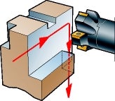
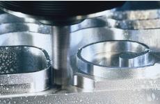
Shoulder milling generates two faces simultaneously, which requires peripheral milling in combination with face milling. Achieving a true, ninety degree shoulder is one of the most important requirements. Shoulder milling can be performed by traditional square shoulder cutters, and also by using end milling cutters, long edge cutters and side and face milling cutters. Due to these numerous options, it is essential to consider the operational requirements carefully in order to make an optimal choice.
Choice of tools
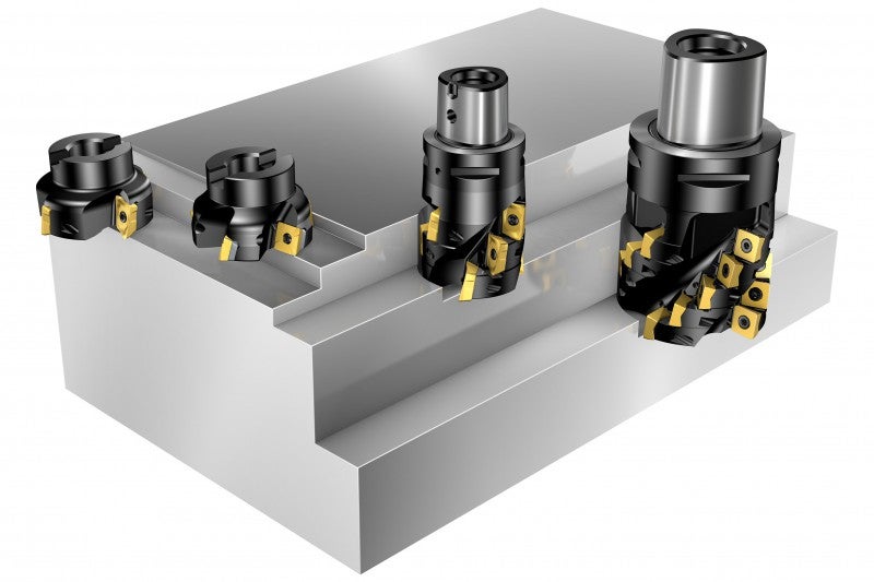
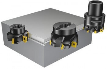
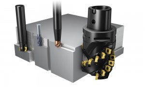
Shoulder milling cutters
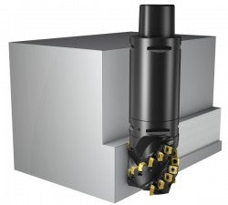
Shoulder face mills of conventional designs are often capable of milling “true”, 90 degree shallow shoulders. Many shoulder face mills are universal cutters, and can be used advantageously for making holes. They offer a good alternative to face milling cutters when milling axially deflecting surfaces or for milling close to vertical faces.
End milling cutters
The indexable insert and solid carbide end mills offer good solutions for shoulders requiring accessibility.
Long edge milling cutters
Long edge cutters are generally used for milling deeper shoulders.
How to apply
Milling of shallow shoulders
This frequently used operation is generally performed by shoulder face mills and end mills. A shallow cut allows for a larger radial cut. Often these cutters can replace face mills, in particular when the axial pressure on the component is a limitation, and when there is a demand for accessibility close to vertical faces or fixture sections. Oversized shoulder cutter options provide for optimal accessibility when milling shallow shoulders located deep.
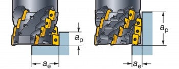
Milling of deep shoulders
Use repeated passes with shoulder face mills and end mills. To minimize surface errors, such as scallops and transition-edges between the passes, a high precision cutter that is able to produce true 90º shoulders is an absolute requirement. If shoulder depth is smaller than 75% of the cutting edge length, the quality of the vertical surface does not normally require extra finishing.
Use a single pass with a long edge milling cutter
A long edge cutter is a good solution for deeper, larger and usually heavier shoulder milling applications. They have a high metal removal capacity, and are generally used for rough milling as the resulting surface texture is characterized by side milling at high feed rates.
These cutters make demands on:
- Stability
- Spindle condition
- Chip evacuation
- Tool holding
- Power
Radial forces are considerable making this a tough side milling application.
Shorter long edge cutters are suitable for:
- Radially large but shallow shoulders.
- Full slotting at a depth equal to the diameter, which can make up for machine limitations
Longer versions are intended for:
- Milling of shoulders with moderate radial depth.
- Edging in powerful, stable machines
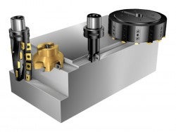
Milling of shoulders located deep
Oversized shoulder cutter options provide for optimal accessibility in milling shallow shoulders located deep. For those shoulders that are located at even larger depths, use extensions with the Coromant Capto coupling. Long edge cutters are also available in oversized versions to be used for deeper shoulders located deep. However, the radial depths of cut are more limited.
Application checklist and hints
- Down-milling is always the first choice, and is especially important for shoulder milling due to the 90° entering angle
- Machining should be performed in a manner that directs the cutting forces towards the support points of the fixture insofar as this is possible. Up-milling can, therefore, be a favorable alternative in some cases
- Selection of cutter pitch is dependant on the stability of the entire system, including: the machine tool, workpiece and its clamping, as well as the workpiece material
- In ISO 40 machines and smaller, coarse-pitch cutters are recommended, due to limited stability
- Coarse-pitch cutters are also recommended for machining components mounted high up on a cube fixture
- The positioning of the cutter on the workpiece is extremely important and should receive extra attention
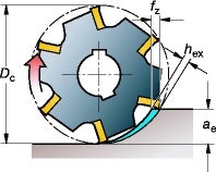
- When DC/ae >10, the feed, fz, should be adjusted in accordance with the hex value to achieve a good result and avoid edge breakdown
- If the shoulder depth is smaller than 75% of the cutting edge length, the quality of the vertical surface does not normally require extra finishing
- Choose a tougher carbide insert grade than for face milling
- If long edge cutters are used, the conditions are demanding, therefore, an even tougher grade may be required
- The deeper the cut, the more important it is to choose a lower cutting speed in order to avoid vibrations
- When vibrations occur, decrease vc and increase fz, check against the recommended hex value!
- Ensure that enough machine power is available for the chosen cutting data
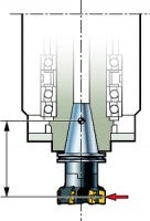
Tool holding
- Pay special attention to power requirements when taking large cuts, particularly with long edge cutters
- Tool mounting has the greatest influence on the milling result for cutters smaller than 50 mm
- The larger the cutting depth, the more important the size and stability of the coupling become: since the radial forces are considerable when using shoulder face mills, particularly long edge milling cutters
- Coromant Capto couplings provide optimum stability and the smallest deflection for all types of cutters – particularly important with long or extended tooling
Rolling into cut
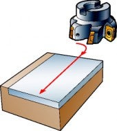
- Smooth entrances into the cut are essential for avoiding vibrations and extending tool life, particularly when milling shoulders
- Program the cutter to roll into cut; always generate a chip thickness on exit that is zero: together this will ensure both, higher feed and longer tool life
- This method is most suitable for applications in which you are milling around external corners, as it avoids sharp changes in the cut
- Keep the cutter engaged in a continuous cut
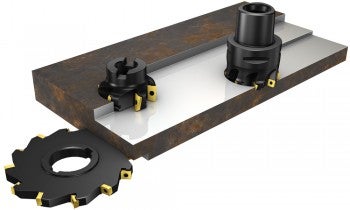
Milling of shoulders using side and face milling cutters
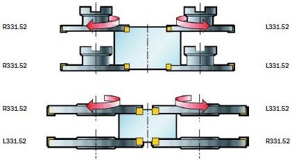
Side and face milling cutters are also used for milling shoulders, particularly if the configuration is narrow yet radially wide. These cutters are often the only possible solution for back-facing of hidden shoulders and faces.
| Right | Left |
 |
Edging peripheral milling
What is successful edging peripheral milling?
Machining an edge is really a side milling operation applied in contouring tool passes. Side milling and edging are options of peripheral milling.
Choice of tools
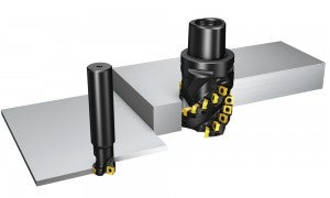
- Thin edges are generally produced by end milling cutters, while deeper or thicker edges are generated by end mills using repeated “shoulder milling” passes, or by long edge cutters in a single pass
- Shoulders with depths of twice the diameter are effectively machined using long edge milling cutters or solid carbide cutters. For such deep shoulders, or thick component edges, a radial depth of cut of 0.5 times the diameter is recommended
- Side and face milling cutters can also be used for edging or peripheral milling
- A large helix ensures a sufficient number of teeth in cut and a smooth cutting action for edging at small radial cutting depths
- A close pitch or extra close pitch type of cutter is especially suitable for edging. This is also true when milling thinner edges or shallow ledge type shoulders using 90º end mills
How to apply
Surface texture – radially generated
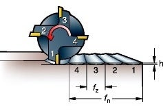
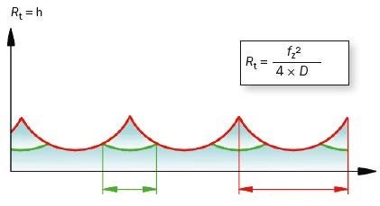
When there is no run-out in the cutter, the height of the cusp, h,
will be equally high and can be calculated using the formula:
Profile depth / cusp height
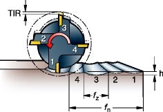
When there is a run-out in the cutter, the feed per tooth, fz,
and consequently the height of the cusp, h, will vary depending on the TIR.
 | |
| fz | fz run-out |
As mentioned, surface texture and climbing tendencies may limit the feed rate, especially when the radial depth of cut is small.
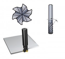
When using the side of an end mill to mill a profile, a series of ‘cusps’ are generated. The height of the cusp, - h, is determined by:
- Cutter diameter, DC
- Feed per tooth, fz
- Tool indicator reading of the run-out, TIR
Indexable insert cutters will always have a higher TIR than solid carbide cutters. Also, the larger the cutter diameter, the greater the number of teeth, which increases the distance between the high and low spots of the cusp.
For best surface finish:
- Use a solid carbide cutter
- Use a high precision power chuck with Coromant Capto coupling
- Use the shortest possible overhang
Feed recommendation (disregard hex):
- Indexable insert cutters, start value fz = 0.15 mm/tooth
- Solid carbide cutters, start value fz = 0.10 mm/tooth
Note: The worst surface quality is achieved if only one cutting edge generates the surface, due to bad run-out of the cutter.
Application checklist and hints
- A critical factor in peripheral milling is achieving a suitable feed per tooth, fz
- The feed value, fz, has to compensate for the cutter engagement, which influences the chip thickness
- Feed per tooth, fz, should be multiplied by the modification factor. This will give a higher feed rate with a smaller arc of engagement, and at the same time ensure that the chip thickness is large enough. However, the modification factor may not always be fully applicable: surface texture and climbing tendencies may limit the feed rate
Shoulder milling of thin deflecting walls
For shoulder milling of:
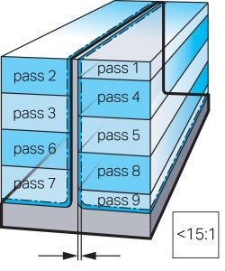
- Small height to thickness ratio < 15:1:
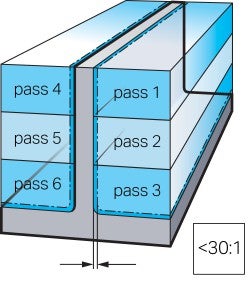
- Moderate height to thickness ratio < 30:1
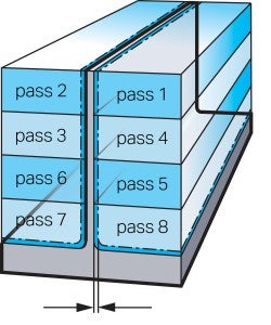
- Very large height to thickness ratio > 30:1
- Thin walled base
Considerations:
- Machining strategies for thin wall sections will vary, depending on height and thickness of the wall
- The number of passes will be determined in all cases by the wall dimensions and the axial depth of cut
- Consider stability of both the cutter and the wall
- Use of high speed techniques, i.e. small ap/ae and high vc, facilitates milling of thin walls, as they reduce the time of tool engagement and consequently, the impulse and the deflection.
- Down-milling should be applied
- Equal methods are used for milling aluminium and titanium
Small height to thickness ratio < 15:1:
The passes should be made in a zig zag path.
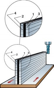
"Thinwall" milling:
- Machine one side of the wall in non-overlapping passes
- Repeat on the opposite side
- Leave an allowance on both sides for subsequent finishing
Moderate height to thickness ratio < 30:1
"Waterline" milling:
- Alternate sides, machining to given depths, in non-overlapping passes
Step support milling:
- A similar approach, but overlap between passes on opposite sides of the wall: this provides more support at the point being machined. The first pass should be at a reduced depth of cut, ap/2
- In either case, leave an allowance on both sides for subsequent finishing of 0.2 – 1.0 mm
Very large height to thickness ratio >30:1
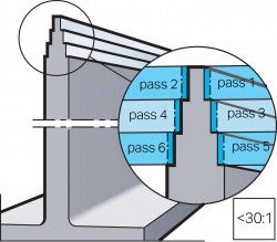
In addition to alternating sides of the wall while machining, approach the desired wall thickness in stages, using a "christmas tree" routine.
- The thinner section is always supported by thicker sections below them as they are machined
- Move down the wall in this stepwise manner
Thin walls
Finishing allowance
Waterline
Finishing allowance
Thin walls
Finishing allowance
Shoulder milling of thin-walled base
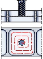
Machining thin bases:
- Use circular ramping at the centre of the base area to required depth
- Mill outwards in a circular ramping path from that point
If this involves milling a surface whose opposite side has already been machined:
- Use a tool with a minimum number of cutting edges
- Apply as little contact pressure to this side as possible
If the component has a hole at the centre of the base:
- Leave a support leg in place when machining the first side
- Machine the second side
- Remove the support leg after both sides have been completed
CoroMill® 490 shoulder milling cutter
CoroMill® 490 milling a shoulder. open_in_new
CoroMill® MS20 - Versatile shoulder milling
CoroMill® MS20 not only handles all types of shoulder milling with ease – thanks... open_in_new
CoroMill® MS20 - Shoulder milling redefined
You shouldn't have to settle for compromises. CoroMill® MS20 is your key to secure... open_in_new
CoroMill MS60 - Versatile face and shoulder milling
Discover the versatility of shoulder milling solution CoroMill® MS60. This dependable... open_in_new
