
Face milling
Face milling operations include:
- General face milling
- High feed milling
- Heavy duty face milling
- Finishing with wiper inserts
General face milling
What is successful face milling?
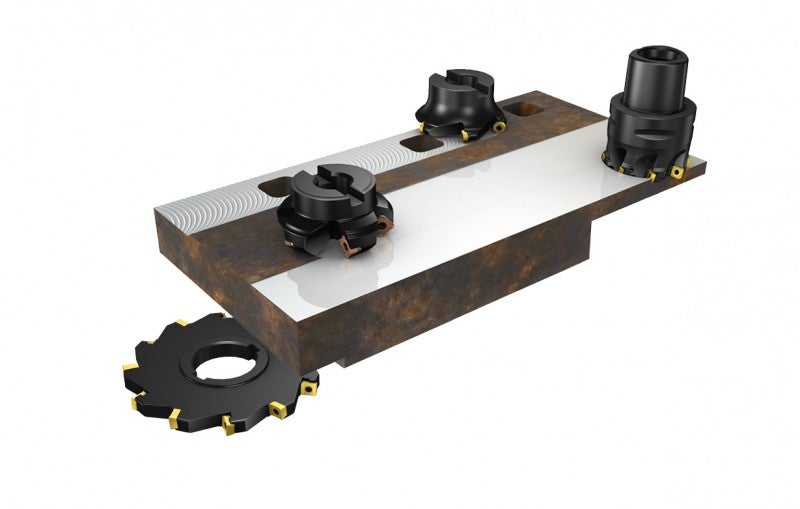
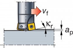
Face milling is the most common milling operation and can be performed using a wide range of different tools. Cutters with a 45º entering angle are most frequently used, but round insert cutters, square shoulder cutters and side and face mills are also used for certain conditions. Be sure to choose the right cutter for the operation for optimal productivity (see information on choice of tools below).
Choice of tools
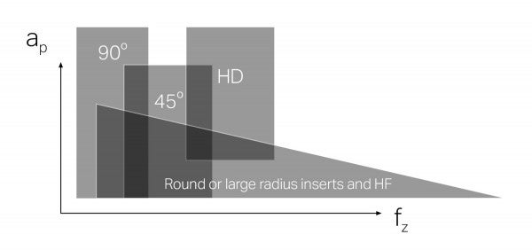
Overview of face milling cutters
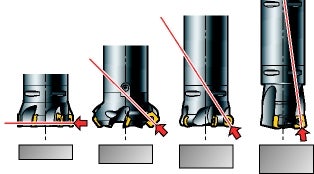
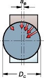
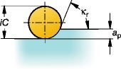
The diagram below shows the main application area for different cutter concepts, in terms depth of cut, ap, and feed per tooth, fz.
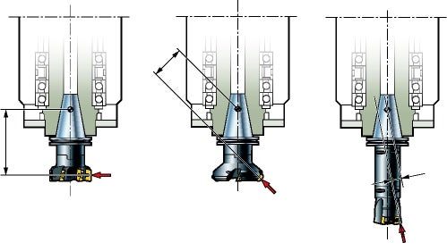
Direction of cutting forces generated by different entering angles.
10° - 65° face and plunge milling cutters
This wide range of cutters are used mainly for face milling operations, but cutters with very small entering angles that are suitable for plunge milling also belong to this group.
45° cutters
- First choice for general purpose
- Reduce vibrations on long overhangs and weak set-ups
- Chip thinning effect allows increased productivity
90° cutters
- Thin walled components
- Weak-fixtured components
- Where 90° form is required
Round insert and large radius cutters
Round insert cutters are very versatile, have excellent ramping capabilities, and are used for both demanding face milling processes as well as profiling operations.
- General purpose cutter
- Strongest cutting edge
- Many edges per insert
- Especially suitable for heat-resistant alloys, ISO S.
- Smooth cutting action
Choice of method - example
Face milling
|
||||||||

|
||||||||
| 25-65° entering angle | 90° entering angle | 10° entering angle | ||||||
|
Advantages + High productivity + Optimized for face milling + Multi edge insert options Disadvantages – Moderate depth of cut |
Advantages + Versatile cutter that can be used for many other operations + Low axial forces
+ Relatively large depth of cut in relation to insert size Disadvantages – Lower productivity |
Advantages + High productivity + Extremely high feed + Axial cutting force direction (favourable for spindle stability) Disadvantages – Low depth of cut |
||||||
|
High productivity
The basic choice |
Versatile
Mixed production |
High productivity
Problem solver |
||||||
How to apply
Intermittent face milling of surfaces with interruptions
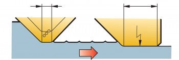
Avoid milling over interruptions
- If possible, avoid milling over interruptions (holes or slots). Such intermittent cuts are demanding on the tool’s cutting edges as they cause multiple entries and unfavourable exits
- Alternatively, reduce the recommended feed rate by 50% over the workpiece area containing the interruptions to keep thin chip when exit cut
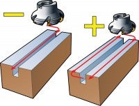
Face milling of thin-walled and deflecting sections
- Consider the direction of the main cutting forces in relation to the stability of the workpiece and fixture
- When milling axially-weak components, use a 90° shoulder milling cutter, which directs the major portion of the cutting forces in an axial direction
- Alternatively, use a light-cutting, face milling cutter
- Avoid axial depths of cut that are smaller than 0.5–2 mm in order to minimize axial forces
- Use a coarse-pitched cutter to obtain the smallest possible number of edges in cut
- Use sharp, positive (-L) edges to minimize cutting forces
- Use a differential pitch cutter as problem solver
Edging of thin sections using face milling cutters
- The cutter should be positioned off centre for face milling operations on the edges of thin sections. The cut becomes smoother and the cutting forces are directed more uniformly along the wall, which reduces the risk of vibration
- Select a cutter pitch that maintains more than one insert in the cut at all times
- Use the lightest insert geometry possible (light instead of medium, or medium instead of heavy)
- Select a smaller insert radius and shorter parallel land to lower the risk of vibration in thin-walled components
- Use low cutting data, small cutting depth, ap, and low feed per tooth, fz
Application checklist and hints
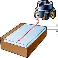
Roll into cut
- Consider machine tool stability, spindle size and type (vertical or horizontal) and available power
- Use a cutter diameter that is 20 to 50% larger than the workpiece
- Consider maximum chip thickness when positioning the cutter for optimum feed
- Position the cutter off centre to produce the thinnest chip at exit
- Apply down-milling for favourable chip formation, i.e. thick to thin chip
- Program the cutter to roll into the cut or reduce the feed to obtain a smooth entry
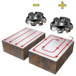
Keep cutter constantly engaged.
- Apply down-milling for favourable chip formation, i.e. thick to thin chip
- Avoid entries and exits through tool path programming
- Frequent entering and exiting the workpiece should be avoided if possible. It can create unfavourable stresses on the cutting edge, or cause dwell and chatter tendencies. It is recommended that you program a tool path that keeps the milling cutter in full contact, rather than performing several parallel passes. When changing direction, include a small radial tool path to keep the cutter moving and constantly engaged
High feed milling
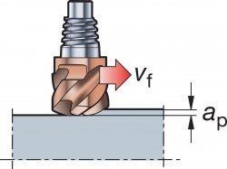
What is successful high feed milling? When machining aluminium, and sometimes when machining cast iron with CBN or ceramic inserts, cutting speeds of more than 1000 m/min can be used, which result in a very high table feed, vf. This type of machining is called High Speed Machining (HSM).
In milling short-chipping materials, such as grey cast iron, a face milling cutter with an extra close pitch can be used, resulting in high table feed. In HRSA materials where cutting speed is normally low, an extra close pitch results in a high table feed.
Face milling with a very high feed per tooth (up to 4 mm/tooth) is possible when using cutters that have small entering angles or when using round insert cutters, due to their chip thinning effect. Although the depth of cut is limited to less than 2.8 mm, the extreme feed makes it a highly productive milling method. Specific cutter concepts are optimized for extreme high feed milling at small axial depths of cut. A small entering angle is the precondition required for applying a light and fast, high feed.
Choice of tools
High feed cutters
| Max. cutting depth (ap), mm | 1.2 - 2 |
| Cutter dia. (DC), mm | 25 - 160 |
| Material |  |
Round insert cutters
| Max. cutting depth (ap), mm | 1.3 |
| Cutter dia. (DC), mm | 10 - 25 |
| Material |  |
Medium HF
| Max. cutting depth (ap), mm | 1.3 | 10 | 7/8 | 2.8 |
| Cutter dia. (DC), mm | 4 - 20 | 25 - 160 | 10 - 42 / 25 - 125 | 63 - 160 |
| Material | | | |  |
High feed cutters:
- Productive high feed face mills with a 10° entering angle, allowing for very high feed per tooth, fz
- High feed rates at small depths of cut, ap
- High precision tools optimized for high speed machining of hardened steel
- Roughing to semi-finishing of contours and asymmetrical configurations at extreme feed rates
Note: For round insert and radius cutters, the ap value should be kept far below the maximum recommended value to allow high feed milling
Round insert cutters:
- Increased chip thinning effect at reduced axial cut
- Smooth cutting action
- General purpose cutters for tough or light conditions
How to apply
Cutters with a small entering angle
Cutters with very small entering angles enable a dramatic increase in the feed, fz, due to the chip thinning effect when ap is small.
| iC | Dimensions, mm | Uncut material | ||
| iC | R | b | ap | x |
| 9 | 2.5 | 7.05 | 1.2 | 0.79 |
| 14 | 3.5 | 12.0 | 2.0 | 1.48 |
Maximum chip thickness is dramatically reduced by a low entering angle. This allows extremely high feed rates to be used without over-loading the inserts.
Note: Avoid machining all the way against a 90° shoulder, because the positive effect of a low approach angle will be lost, i.e. the depth of cut will dramatically increase.
As always, the feed rate has to be reduced and adapted depending upon specific conditions and to avoid vibrations, which can damage the inserts.
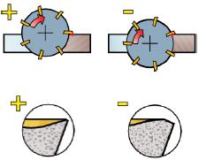
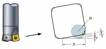
Round insert cutters
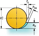
Chip thickness, hex, varies with round inserts and depends on the depth of cut, ap. When using high feed milling techniques with a round insert cutter, the depth of cut should be kept low (max. 10% of insert diameter, iC, otherwise the chip thinning effect is reduced and the feed has to be decreased, see illustration).
Note: When using round insert cutters, it is important to reduce the feed when approaching a wall/shoulder, because the depth of cut suddenly increases.
Strong inserts for general roughing
On round inserts, the chip load and entering angle vary with the depth of cut. The best performance is achieved when the depth of cut is smaller than 25% x insert diameter, iC.
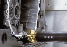
Heavy duty face milling
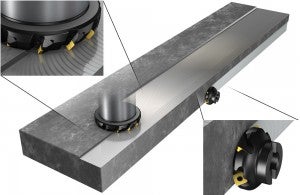
What is successful heavy duty face milling?
Heavy duty face milling applications include rough milling of heavy forged or hot rolled material blanks, castings, and welded structures in large gantry mills and powerful milling machines, or machining centres. Large amounts of material have to be removed, generating high temperatures and high cutting forces, which places specific demands on the milling inserts:
- Heavy loads on the main edge at full depth of cut
- Wear at the corner by the abrasive scale when cutting depth approaches zero
A 60º entering angle is optimal for a heavy duty milling cutter. This design provides:
- Good depth of cut capacity, relatively even cutting forces and a chip thinning effect that allows for high feed rates
- The axial allowance of the design allows the insert to have a generous parallel land, which generates good surface finishes
Choice of tools
Heavy duty face milling cutters
| Entering angle (κr), mm | 60° | 45° | 90° | Round inserts |
| Max. cutting depth (ap), mm | 13/18 | 10 | 15.7 | 12.5 |
| Cutter dia. (DC), mm | 160 - 500 | 80 - 250 | 40 - 200 | 66 - 200 |
| Material |  | | |  |
60° Heavy duty milling cutters
- Designed for efficient tool handling, which results in short down-time and secure, quick insert indexing in the machine
- Cut capability up to 18 mm, for good metal removal and machining of uneven, wavy surfaces
- High productivity – feed rates of 0.4 – 0.7 mm per tooth
- Generous parallel land for good semi-finishing results
- Strong insert corner to resist abrasive surface scale at small depths of cut
- Cutter strength, for security in very demanding cuts
45-90° Medium duty milling cutters
- A medium duty face mill that provides the lightest cutting ability
- Capable of cutting depths of 6–8 mm within a feed range of 0.2 – 0.6 mm
- For tough conditions in larger machining centres
- Can be used with wiper inserts for milling surfaces with good finishes
- First choice for medium duty face and shoulder milling
Large round inserts cutters
- A medium duty cutter with strong edges for tough conditions, like milling through scale and interruptions. The round insert geometry provides a smooth cutting action
- Eight cutting edges can be utilized under favourable conditions
- Maximum depth of cut is 10 mm. The maximum recommended chip thickness varies widely up to 0.55 mm per tooth, depending on the insert geometry and depth of cut
How to apply
In heavy duty applications, large insert cutters with large diameters are used. Cutting speed is normal, but high ap and fz, combined with a large ae, make it very productive.
Entrance into cut
Because of the tough conditions common in heavy duty milling, the entrance into the cut is often critical.
- If possible, program the tool path for rolling into the cut
- If not possible, reduce the feed until the cutter is fully engaged
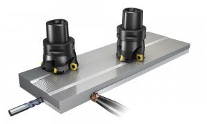
Cutter position and size
In heavy duty milling where several passes need to be performed to mill a large surface, it is important to follow the recommendations regarding:
- Cutter position and engagement
- Cutter size in relation to machine tool capacity
- Tool path, to avoid unfavourable exits
Be observant of high temperatures
Demanding, heavy duty milling generates high temperatures. When magnetic tables are used to clamp the component, the large volumes of chips that are produced will often be retained around the cutter. This causes interrupted or partial chip evacuation and re-cutting of chips, which are hazardous for tool life. To avoid this, keep the working area free of chips. Prevent the vulnerable insert corners from rubbing against abrasive skin and scale by increasing the depth of cut to move the surface contact point closer to the stronger main edge of the insert.
Note: When mounting indexing inserts with a cutter, use gloves to avoid injury due to heat.
Finishing with wiper inserts

How to achieve successful surface finishes in face milling operations
Excellent surface finishes can be achieved with standard inserts in combination with one or more wiper inserts. Wiper inserts work most usefully at a high feed per revolution, fn, in larger diameter cutters with extra close pitch and setting facilities.
Feed per revolution can be increased approximately four times while still maintaining good surface quality. Wiper inserts can be used when face milling most materials to produce good surface textures – even under unfavourable conditions.
Choice of tools
Cutters
| Entering angle (Kr), mm | 45° | 45° | 65° | 90° | 25° | 90° |
| Max. cutting depth (ap), mm | 6 | 10 | 6 | 10 | 0.9 | 8.1 |
| Cutter dia. (DC), mm | 40 - 250 | 32 - 250 | 40 - 250 | 40 - 200 | 80 - 250 | 125 - 500 |
| Surface finish (Ra) | < 1.0 | < 1.0 | < 1.0 | < 1.0 | < 1.0 | < 1.0 |
| Material | | | | |  | |
Wiper edge inserts are available in different length (Bs) and often in right and left hand version on each insert. Grades are available for most work piece materials. Adjustable inserts seats are common for specific inserts seats when cutter concept are developed specially for finishing operations or offer solutions with cassettes.
How to apply
In a finishing operation with a large face milling cutter, the feed, fz, usually needs to be kept low. However, by using a cutter with wiper inserts, the feed can be increased 2-3 times without sacrificing surface quality.
Mirror finish at high feeds
| Surface roughness | ||

|
Feed fn | |
| fn1 <= 0.8 * bs1 | fn2 <= 0.6 * bs2 | |
A : Standard inserts only
B : With one Wiper insert
C : fn = feed / revolution
| bs1 | bs2 | |
|
||
- When fn exceeds 80% of the length of the parallel land, Bs, on standard inserts, a wiper edge will improve surface quality
- When using large cutter diameters with a high number of inserts, the need for wiper inserts to maintain surface finish becomes essential when feed per revolution, fn, increases
- The cutter's axial run-out, which depends on spindle inclination, cutter size, mounting and the accuracy of its setting, influences the waviness of the machined surface. The crowned wiper land will compensate for this and produce a step-free surface. A feed per revolution limited to 60% of the wiper land will ensure this
- A wiper land protrudes below the milling inserts by approximately 0.05 mm when mounted on cutters with fixed insert seats. For cutters of cassette design, the wiper edge can often be adjusted to this position with great accuracy. The protrusion subjects wiper inserts to greater loads than conventional inserts, which can lead to vibration. Therefore, wipers should be used for light machining at moderate cutting depths and in limited numbers
- Depth of cut should be light in order to limit axial forces and reduce the risk of vibration. In finishing, the recommended axial depth of cut is 0.5 – 1.0 mm
- Extra care is required when mounting a wiper insert in order to correctly position its long edge
Example:
- The width of the parallel land, Bs, on the insert is 1.5 mm
- There are 10 inserts in the cutter, and the feed per tooth, fz, is 0.3 mm. Feed per revolution, fn, will therefore be 3 mm (twice the length of the parallel land)
- To ensure a good surface finish, feed per revolution should be a maximum of 80% of 1.5 mm = 1.2 mm
- A corresponding wiper insert will have a parallel land with a width of approximately 8 mm
- Result: Feed per revolution could be increased from 1.2 mm to 60% of 8 mm = 4.8 mm
Note: Other limitations, such as machine power, must be taken into consideration.
Application checklist and hints
Hints for achieving a “mirror finish”:
- Use high cutting speed and/or Cermet inserts to obtain a shiny surface
- Use cutting fluid or oil mist for sticky ISO M and S materials
- PVD-coated inserts with sharp edges and an ap of 0.5 – 0.8 mm produce the best surface finish
- Strive to use the same grade in wiper insert that are used as working inserts
Multi-edge face milling operations with CoroMill 745
A double-sided face milling cutter with positive cutting action, CoroMill 745 offers... open_in_new
M5B90 - Aluminium face milling cutter
Technical animation open_in_new
CoroMill MS60 - Versatile face and shoulder milling
Discover the versatility of shoulder milling solution CoroMill® MS60. This dependable... open_in_new
Developing a face milling cutter for aluminum - Passion for innovation
The face milling cutter for aluminum - M5B90 - is a result of true innovation. Meet... open_in_new
